
User Guide


Technical Instructions Flowrite VF 599 Series Three-Way Valves
Document Number 155-185P25
April 9, 2007
Page 10 Siemens Building Technologies, Inc.
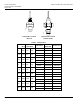
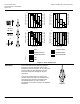
Dimensions
The letters in Figure 6 refer to actuator and service envelope dimensions in Table 7.
See Table 8 for valve body dimensions.
W
H
VF0166R1
W
1
H
1
Figure 6.
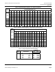
Table 8. Dimensions of the Actuator and Recommended Service Envelope.
Dimensions in Inches (millimeters).
Actuator
Actuator
Prefix
Code
Actual
Height of
Actuator
H1
Service
Height
H
Actual Width or
Diameter of
Actuator
W1
Service
Width
W
4-inch
Pneumatic
268, 269
270
5-3/4 (146)
14
(350)
5-1/2 (137)
diameter
18
(450)
8-inch
Pneumatic
277, 278
283, 284
14-1/8
(359)
26
(660)
8-3/4 (222)
diameter
21
(533)
12-inch
Pneumatic
279, 285 17-7/8
(454)
30
(762)
15-1/8 (384)
diameter
27
(686)
SKB
285, 190,
291
14-3/4
(375)
22-3/4
(578)
14×9 (335 ×228)
25
(635)
SKD
274, 275
276
11-13/16
(300)
19-3/4
(500)
5 (127) Width
6-5/8 (169) Depth
14-1/2
(360)
SQX
271, 272
273
8-7/8 (226) 17
(430)
5-17/32 (140) W
4-3/8 (111) Depth
13-1/2
(340)
El/Mech with
linkage
295, 296
297
11 (280) 22
(559)
5-3/4 (144) Width x
8-7/8 (225) Depth
25-3/4
(654)