
Brochure
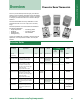
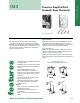

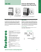
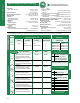
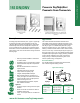
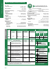
Table Of Contents
- Table of Contents/TIs
- Pneumatic Room Thermostats-Powerstar
- Pneumatic Room Thermostats- D Series
- Pneumatic Thermostats for Specialized Applications
- Pneumatic Relative Humidity Sensors
- Electric Room Thermostats/Controllers
- Low Voltage Wall Thermostats
- Line Voltage Remote Bulb Thermostats
- Line Voltage Room Thermostats-Heating/Cooling
- RAA... Room Thermostats
- RAB... Fan Coil Thermostats
- RCC... Room Temperature Controllers for 2-pipe Fan Coil Units
- RCC... Free Energy Band Room Temperature Controllers for 4-pipe Fan Coil Units
- RCU50... Room Temperature Controllers for CAV and VAV Systems
- RCU61 Room Temperature Controllers for CAV and VAV Systems
- RDU... Room Temperature Controllers with LCD for Heating/Cooling Systems
- RDX... Room Temperature Controllers with LCD
- Electric Thermostats for Specialized Applications
- Accessories and Service Kits

A-6
Specifications/Product Ordering
Thermostats & Hygrostats
192 S
Scale; Range
Major (minor) Divisions ............................................ 45 to 85°F, 10(2)°F
(7 to 30°C, 5(1)°C)
Factory Calibration .....................................................72°F, 7.5 psig ±0.3
(22°C, 52 kPa @ 1.8)
Sensitivity Adjustment Range .................1 to 4 psi/°F (12 to 50 kPa/°C)
Factory Setting ....................................................2.5 psig/°F (31 kPa/°C)
Limit Stop
Field Adjustment Range .............................................. 45/85°F (7/30°C)
Fixed Limit Stop Range ............................................. 55/75°F (13/24°C)
Temperature
Storage ......................................................-10 to +140°F (-23 to +60°C)
Ambient Operating .......................................... 40 to 140°F (4 to 60°C)
Accuracy at Factory
Calibration ........................................................................ ±2°F (±1.1°C)
Response ........................................................................ 0.1°F (0.06°C)
Supply Air Pressure
Recommended ........................................................... 25 psig (172 kPa)
Maximum .................................................................... 30 psig (207 kPa)
Nominal Air Consumption for Air Compressor Sizing
1-pipe ......................................................................... 25 scim (6.8 ml/s)
2-pipe ......................................................................... 20 scim (5.5 ml/s)
Nominal Air Capacity for Air Main Sizing
1-pipe ......................................................................... 25 scim (6.8 ml/s)
2-pipe ......................................................................... 20 scim (5.5 ml/s)
Nominal Chassis Air Capacity
1-pipe Supply ............................................................. 25 scim (6.8 ml/s)
2-pipe Supply ............................................................ 230 scim (63 ml/s)
1-pipe Exhaust .............................................................. 30 scim (8 ml/s)
2-pipe Exhaust .......................................................... 150 scim (41 ml/s)
Air Connections ..................................................5/32” (4 mm) OD tubing
Dimensions (with cover) ..............................2.16” W x 3.34” H x 1.59” D
(55 mm W x 85 mm H x 40 mm D)
Shipping Weights (with cover)
Thermostat Chassis and Wall Plate ............................ 0.53 lb. (0.24 kg)
Plastic Cover/Metal Cover ............... 0.07 lb. (0.04 kg)/0.27 lb. (0.12 kg)
Page
76
For complete conversion kits, refer to the
Retroline
®
Retrostats starting on page A-15.
Thermostat Chassis
Model # Thermostat Chassis Type & Wall Plate
Air Output Thermometer &
Output Set Point Capacity Set Point Scales Control Action
Direct Reverse
192 S Single Single Low °F 192-200 192-201
1-pipe (Heat or Cool) (No Relay) °C 192-220 192-221
192 S Single Single High °F 192-202 192-203
2-pipe (Heat or Cool) (Integral Relay) °C 192-222 192-223
Cover Description Plastic Metal
• Adjustment set point concealed 192-257 192-357
• Indicator set point concealed
• Chassis thermometer concealed
• No logo
• Adjustment set point concealed 192-256 192-356
• Indicator set point concealed
• Chassis thermometer concealed
• With logo
• Adjustment set point concealed 192-254 192-354
• Indicator set point concealed
• Chassis thermometer exposed
• Adjustment set point key 192-265 192-365
• Indicator set point exposed
• Chassis thermometer concealed
• Use with 1/2” set point knob option
• Adjustment set point key 192-266 192-366
• Indicator set point exposed
• Chassis thermometer exposed
• Use with 1/2” set point knob option
• Adjustment set point exposed
• Indicator set point exposed 192-250 192-350
• Chassis thermometer concealed
• Adjustment set point exposed 192-252 192-352
• Indicator set point exposed
• Chassis thermometer exposed
Thermostat Covers
Sold Separately
Ordering Notes
• “Exposed features” are indicated in green on corresponding illustration.
• For 194 refer to Powerstar Retroline section.
Code Color
(add suffix to Part No.)
None Desert Beige (standard)
W White
METAL COLORS
Code Color (add suffix to part No.)
A #1 Silver
B #5 Satin Chrome
C #7 Light Statuary Bronze
D #10 Special Bronze
E
Brushed Electroplated Satin Chrome
F Sierra Gold
G Brushed Aluminum
H White
Cover Options
PLASTIC COLORS
Code Description
(add suffix to Part No.)
K Chassis with 1/2” (13 mm)
diameter set point adjustment
knob for convalescent facilities.
For Horizontal Cover, refer to the
Accessories and Service Kits section.
Chassis Options
For Color Chip Samples,
order 152-178P10.
Options Color
Thermostat Covers
Page
76