
Brochure
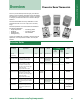
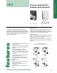

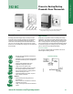
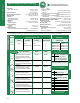
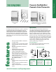
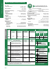
Table Of Contents
- Table of Contents/TIs
- Pneumatic Room Thermostats-Powerstar
- Pneumatic Room Thermostats- D Series
- Pneumatic Thermostats for Specialized Applications
- Pneumatic Relative Humidity Sensors
- Electric Room Thermostats/Controllers
- Low Voltage Wall Thermostats
- Line Voltage Remote Bulb Thermostats
- Line Voltage Room Thermostats-Heating/Cooling
- RAA... Room Thermostats
- RAB... Fan Coil Thermostats
- RCC... Room Temperature Controllers for 2-pipe Fan Coil Units
- RCC... Free Energy Band Room Temperature Controllers for 4-pipe Fan Coil Units
- RCU50... Room Temperature Controllers for CAV and VAV Systems
- RCU61 Room Temperature Controllers for CAV and VAV Systems
- RDU... Room Temperature Controllers with LCD for Heating/Cooling Systems
- RDX... Room Temperature Controllers with LCD
- Electric Thermostats for Specialized Applications
- Accessories and Service Kits

A-10
Specifications/Product Ordering
Thermostats & Hygrostats
Scale; Range
Major (minor) Divisions ............................................ 45 to 85°F, 10(2)°F
(7 to 30°C, 5(1)°C)
Factory Calibration .............................................................72°F, 7.5 psig
(22°C, 31 kPa)
Sensitivity Adjustment Range .................1 to 4 psi/°F (12 to 50 kPa/°C)
Factory Setting .................................................... 2.5 psig/°F (31 kPa/°C)
Limit Stop
Field Adjustment Range .............................................. 45/85°F (7/30°C)
Fixed Limit Stop Range ............................................... 55/75°F (3/24°C)
Temperature
Storage ......................................................-10 to +140°F (-23 to +60°C)
Ambient Operating .......................................... 40 to 140°F (4 to 60°C)
Accuracy at Factory
Calibration ........................................................................ ±2°F (±1.1°C)
Response ........................................................................ 0.1°F (0.06°C)
Supply Air Pressure
Two Pressure
Day (recommended) .............................................. 18 psig (124 kPa)
Night (recommended) ............................................ 25 psig (172 kPa)
Vent-Day/Night ............................... 0 psig (0 kPa)/25 psig (172 kPa)
Two Pressure
Day (range) ....................................... 15 to 19 psig (103 to 131 kPa)
Night (range) ..................................... 23 to 30 psig (159 to 207 kPa)
Two Pressure (Honeywell Competitive Model)
Day/Night .................................... 13 psig (90 kPa)/18 psig (124 kPa)
Two Pressure (Johnson Controls Competitive Model)
Day/Night .................................. 15 psig (103 kPa)/20 psig (138 kPa)
Nominal Air Consumption for
Air Compressor Sizing ................................................ 25 scim (6.8 ml/s)
Nominal Air Capacity for Air Main Sizing ................... 40 scim (11 ml/s)
Nominal Chassis Air Capacity
Supply ....................................................................... 230 scim (63 ml/s)
Exhaust ..................................................................... 150 scim (41 ml/s)
Air Connections .................................................... 5/32” (4 mm) OD tube
Dimensions (with cover)
192 DN ........................................................2.16” W x 3.34” H x 1.59” D
(55 mm W x 85 mm H x 40 mm D)
192 DNV ........................................................2.5” W x 3.34” H x 1.59” D
(64 mm W x 85 mm H x 40 mm D)
Shipping Weights
Thermostat Chassis and Wall Plate ............................ 0.53 lb. (0.24 kg)
Plastic Cover .............................................................. 0.07 lb. (0.04 kg)
Metal Cover (dual) ....................................................... 0.27 lb. (0.12 kg)
Thermostat Chassis
Model # Thermostat Chassis Type & Wall Plate
Air Output Thermometer &
Output Set Point Capacity Set Point Scales Control Action
D (DA)/ D (RA)/ D(DA)/
N (DA) N (RA) N (DA)
(with Night Vent)
Single Dual High °F 192-204 192-205 192-206
(Day and Night) (Integral Relay) °C 192-224 192-225 192-226
Ordering Notes
• DNV 3-pipe model provides full air supply on R2 vent port during night control cycle.
• “Exposed features” are indicated in green on corresponding illustration.
• For 194 refer to Powerstar Retroline section.
192 DN
192 DNV
3-pipe
Cover Description Plastic Metal
• Adjustment set point concealed 192-262 192-362
• Indicator set point concealed
• Chassis thermometer concealed
• Adjustment set point concealed 192-264 192-364
• Indicator set point concealed
• Chassis thermometer exposed
• Adjustment set point key 192-269 192-369
• Indicator set point exposed
• Chassis thermometer concealed
• Use with 1/2” set point knob option
• Adjustment set point key 192-270 192-370
• Indicator set point exposed
• Chassis thermometer exposed
• Use with 1/2” set point knob option
• Adjustment set point key (night)
exposed (day) 192-271 192-371
• Indicator set point exposed
• Chassis thermometer exposed
Thermostat Covers
Sold Separately
Code Color (add suffix to Part No.)
None Desert Beige (standard)
W White
METAL COLORS
Code Color (add suffix to part No.)
A #1 Silver
B #5 Satin Chrome
C #7 Light Statuary Bronze
D #10 Special Bronze
E
Brushed Electroplated Satin Chrome
F Sierra Gold
G Brushed Aluminum
H White
Cover Options
PLASTIC COLORS
Code Description (add suffix to Part No.)
K Chassis with 1/2” (13 mm)
diameter set point adjustment
knob for convalescent facilities.
Chassis Options
For Color Chip Samples,
order 152-178P10.
Options
For complete conversion kits, refer to the
Retroline
®
Retrostats starting on page A-15.
Color
Page
76
Page
76
192 DN/DNVThermostat Covers