
Data Sheet for Product

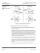
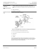
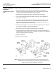
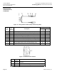
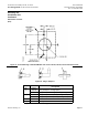
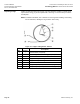

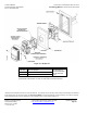
Table Of Contents

Technical Bulletin Accessories for Installing TH 192, TH 194 or
Document Number 155-244P25 Free Energy Band TH 193 HC Room Thermostats
Rev. 2, December 2001
Page 14 Siemens Industry, Inc.
Drywall Installation,
continued
Installation after drywall
is up
A typical installation procedure consists of the following steps:
1. Place the template (D) on the wall at the desired location. The template has
adhesive on the back, protected by paper; remove the paper backing and make
sure the template is level before it sticks to the wall surface.
2. Drill two 5/32-inch diameter holes for No. 6 wall plate mounting screws.
3. Use a 1-1/4 inch diameter hole saw to drill an access hole in the drywall where
indicated on the template.
4. For 5/8-inch thick drywall, insert the clips (B) with the long leg going through the
1-1/4 inch access hole. Make sure they rest flat against the back surface of the
drywall. The wall is held between the two legs of the spring clips. Align the screw
holes in the clips (B) with the holes on the wall.
5. Fish the air lines through the 1-1/4 inch access hole (using tubing kit No. 192-481,
or any tubing kit suitable for finished wall installation).
6. Remove the air link and install the plug-in adapters on the wall plate.
7. Install the wall plate on the wall using the screws (A). Note that the wall plate has
key slotted holes to allow insertion of the screws prior to installation of the wall plate
and also to allow leveling of the wall plate.
8. Attach the thermostat.
The installation is now complete.
NOTE: Adapter frame, Part Number 192-308, may be used in conjunction with the
adapter base to cover up oversized holes, paint lines, broken walls, spots etc.
Figure 13. Electrical Box Wall Plate Installation.