
Data Sheet for Product

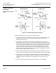
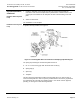
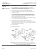
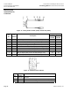
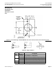
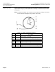

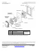
Table Of Contents

Technical Bulletin Accessories for Installing TH 192, TH 194 or
Document Number 155-244P25 Free Energy Band TH 193 HC Room Thermostats
Rev. 2, December 2001
Page 12 Siemens Industry, Inc.
Drywall Installation,
Continued
Rough-in before drywall
is up
Figure 11. Drywall Mounting Bracket Positions.
A typical installation procedure consists of the following steps:
1. Attach the drywall mounting bracket (D) to the stud per the position selected at the
desired location. The "V" notch on the bracket indicates the centerline of the
instrument to be mounted.
2. Make all air line connections to the bracket. For installations with 1/4-inch O.D.
polyethylene tubing, it is necessary to use tubing terminal kit No. 192-481 to adapt to
the connections at the wall plate. In this case, after the tubing terminal kit is attached
to the 1/4-inch tubing, it must be tied to the Locator (E) using wire tie (J) provided.
Leave at least four to six inches of slack in the terminal tubing since it must be
pulled into the room at a later stage to attach it to the wall plate. Notify the drywall
installer to make a square hole (1-5/8 inch × 1-5/8 inch) in the drywall so the Locator
(E) can project through the wall into the room.
4. After the drywall is finished, remove the locator (E) using a screwdriver to remove
the two screws (A) and lightly rock the locator while pulling to free it from the drywall.
5. Removal of the Locator will pull out the terminal tubing. The terminal tubing has a
supply (blue) and a return plug-in adapter connected with an air link. This provides a
pressure-tight connection between the supply and return for testing air lines for
leakage.
6. Remove the air link (K) and install the plug-in adapters (L) on the wall plate.