
Data Sheet for Product


Technical Bulletin Powers Controls TH 192 Adapter Kits
Document Number 155-231P25
Rev. 2, December, 2001
Page 8 Siemens Industry, Inc.
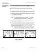
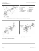
Required Parts For Installation
F. (2) Tube Retainer
G. (2) 5/32-inch (4 mm) Plastic Tube (Polyethylene- Hard) and Coil
H. Multi-slotted Plate
J. (2) No. 6-32 × 1-inch Binder Head Screw
*L. Adapter Base
*P. (2) Plug-in Adapter
*Items not shown. See Figure 2 for proper installation.
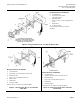
Required Parts For Installation
A. Terminal Plate (11-Hole)
B. (2) Terminal Fitting
C. (2) Holder
D. (2) Gasket
E. (2) No. 6-32 × 9/16-inch Flat-head Screw
F. (4) Tube Retainer
G. (2) 5/32-inch (4 mm) Plastic Tube (Soft) and Coil
H. Multi-slotted Plate
J. (2) No. 10 Sheet 6 –32 × 1-1/2 inch Pan Head Screws
*L. Adapter Base
*P. (2) Plug-in Adapter
*Items not shown. See Figure 2 for proper installation.
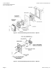
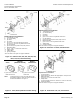
Figure 11. Honeywell TP 410, 910 To 924, 933
Mortar Joint.
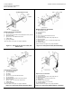
Figure 12. Honeywell TP 901A, B Flush Fitting.
Required Parts For Installation
A. Terminal Plate (11-hole)
B. (2) Terminal Fitting
C. (2) Holder
D. (2) Gasket
E. (2) No. 6-32 × 9/16 inch Flat-head Screw
F. (4) Tube Retainer
G. (2) 5/32-inch (4 mm) Plastic Tube (Soft) and Coil
H. Multi-slotted Plate
J. (2) No. - 6-32 × 1-1/2 inch Pan Head Screws
*L. Adapter Base
*P. (2) Plug-in Adapter
*Items not shown. See Figure 2 for proper installation.
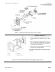
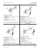
Required Parts For Installation
F
. (2) Tube Retainer
G. (1) 5/32-inch (4 mm) Plastic Tube (Soft) and Coil
H. Multi-slotted Plate
J. (2) No. 6-32 × 1-1/2 inch Pan Head Screw
*L. Adapter Base
M. (2) Rubber Connecting Tube
N. (1) Tubing Adapter (1/4 × 5/32-inch)
*P. (2) Plug-in Adapter
*Items not shown. See Figure 2 for proper installation.
Figure 13. Honeywell TP 901A, B Plaster Back. Figure 14. Honeywell TP901C Mullion or Partition.