
Data Sheet for Product


Technical Bulletin Powers Controls TH 192 Adapter Kits
Document Number 155-231P25
Rev. 2, December, 2001
Page 2 Siemens Industry, Inc.
General Procedure,
Continued
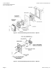
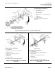
7. Place the multi-slotted metal plate into the plastic frame (plastic frame may or may
not be needed), and attach to the terminal head or the wall using the screws and
slots indicated.
8. Obtain the thermostat mounting plate and screws from the thermostat box.
9. Loosely screw adapter base to multi-slotted plate.
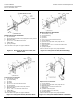
10. Draw plastic tubing through the multi-slotted plate, adapter base and install plug-in
adapters on wall plate.
11. Using the key slotted holes, install wall plate on adapter base and fasten screws to
secure wall plate and adapter base.
12. Carefully plug in thermostats to wall plate.
NOTE: To facilitate plugging the thermostat into O-rings in the adapter, wet or
moisten the thermostat supply and return ports. This wetting or
moistening will lubricate and allow the thermostat to slip through the
O-rings more easily.
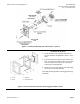
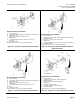
7. Install thermostat cover using Allen hex key tool P/N 192-497 to drive the two
screws that hold the cover in place.
8. When removing the thermostat from the wall plate, hold the thermostat firmly at the
top and bottom and start to pull the thermostat from the wall plate. At the same
time, use a screwdriver to pry wall plate latch arm away from the thermostat chassis
to release it. Do the same for the other side of the thermostat and pull the
thermostat away from the wall plate.
NOTE: Frequent removal and installation of the thermostat may bend the latch
arms beyond their operating positions. If this happens, bend the latch
arms back to their operating position before mounting the thermostat.
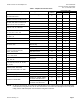
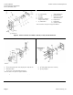
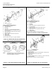
192-300 Universal Kit 192-483 Adapter Kit "A" 192-484 Adapter Kit "B"
Figure 1. Adapter Kits.