
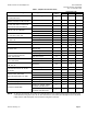
Data Sheet for Product


Powers Controls TH 192 Adapter Kits Technical Bulletin
Document Number 155-231P25
Rev. 2, December, 2001
Siemens Industry, Inc. Page 11
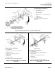
Required Parts for Installation
F. (4) Tube Retainer
G. (2) 5/32-inch (4 mm) Plastic Tube (soft) and Coil
H. Multi-slotted Plate
J. (3) No.8 × 1-1/4 inch Sheet Metal Screw
*K. Adapter Frame (if required)
*L. Adapter Base
M. (2) Rubber Connecting Tube
N. (2) Tubing Adapter (5/32-inch × 5/32-inch or 1/4-inch ×
5/32-inch)
*P. (2) Plug-in Adapter
*Items not shown. See Figure 2 for proper installation.
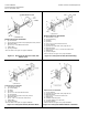
Required Parts for Installation
A. Terminal Plate (11-hole)
B. (2) Terminal Fitting
C. (2) Holder
D. (2) Gasket
E. (2) No. 5-40 × 3/4-inch Rod
F. (4) Tube Retainer
G. (2) 5/32-inch (4 mm) Plastic Tube (Soft) and Coil
H. Multi-slotted Plate
J. (4) No. 5-40 Hex Nut and Washer
*L. Adapter Base
*P. Plug-in Adapter
*Items not shown. See Figure 2 for proper installation.
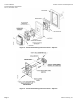
Figure 23. Robertshaw H 10, 50, 52, T15, 16, 21, 25,
26, 30, 51, 52 Surface Fitting.
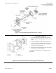
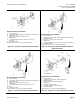
Figure 24. Robertshaw H 10, 50, 52, T15, 16, 21, 25,
26, 30, 31, 51, 52 Mortar Joint.
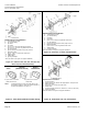
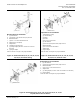
Required Parts for Installation
F. (4) Tube Retainer
G. (2) 5/32-inch (4 mm) Plastic Tube (Soft) and Coil
H. Multi-slotted Plate
J. (2) No. 5-40 × 1-inch Pan Head Screw
*L. Adapter Base
N. (2) Tubing Adapter (1/4-inch × 5/32- inch or 5/32-inch × 5/32-inch)
*P. Plug-in Adapter
*Items not shown. See Figure 2 for proper installation.
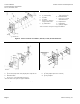
Figure 25. Robertshaw H 10, 50, 52, T15, 16, 21, 25, 26, 30, 31, 51, 52
Drywall, Mortar Joint or Surface.