
Data Sheet for Product
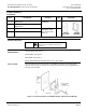
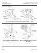
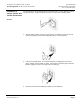
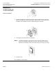
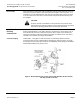
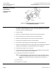
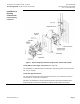
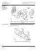
Table Of Contents

Technical Bulletin Accessories for Installing TH 192, TH 194 or
Document Number 155-244P25 Free Energy Band TH 193 HC Room Thermostats
Rev. 2, December 2001
Page 8 Siemens Industry, Inc.
Installation in Existing
Construction
Concealed Piping,
Continued
Figure 6. Mounting Wall Plate and Thermostat with Kit
Nos. 192-481 and 192-685.
Exposed Piping
• For exposed piping installations, use Kit No. 192-479 and adapter Kit No. 192-483.
See Figure 7. A typical installation procedure to mount the thermostat to the surface
of the wall consists of the following steps:
1. Install the tubing.
2. Attach the multi-slotted metal plate using the screws and slots indicated.
3. Notch the adapter base as required to fit over the exposed tubing.
4. Obtain the thermostat wall plate and screws from the thermostat box.
5. Loosely screw the adapter base to the multi-slotted plate.
6. Draw the plastic tubing through the multi-slotted plate and the adapter base.
7. Remove the straight adapters from the plastic tubing and install 90° plug-in adapters
provided in the 192-483 kit. Use the blue adapter for the air supply line.
8. Install the plug-in adapters on the wall plate.
9. Using the key slotted holes, install the wall plate on the adapter base and fasten the
screws to secure the wall plate and the adapter base.
10. Carefully plug the thermostat into the wall plate.
NOTE: To facilitate plugging the thermostat into the O-rings in the adapter, wet or
moisten the thermostat supply and return parts. This wetting or moistening
will lubricate and allow the thermostat to slip through the O-rings more
easily.
11. Install the cover.
The installation is now complete.