
Data Sheet for Product
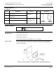
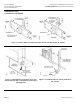
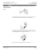
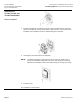
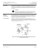
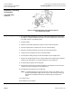
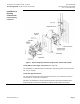
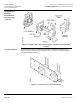
Table Of Contents

Accessories for Installing TH 192, TH 194 or Technical Bulletin
Free Energy Band TH 193 HC Room Thermostats Document Number 155-244P25
Rev. 2, December, 2001
Siemens Industry, Inc. Page 7
Disassembly
When removing the thermostat from the wall plate, hold the thermostat firmly at the top
and bottom and start to pull the thermostat from the wall plate. At the same time, us a
screwdriver to pry the wall plate latch arm away from the thermostat chassis to release
it. Do the same for the other side of the thermostat and pull the thermostat away from
the wall plate.
CAUTION:
Frequent removal and installation of the thermostat may bend the latch
arms beyond their operating positions. If this happens, bend the latch arms
back to their operating position before mounting the thermostat.
Installation in
Existing
Construction
Concealed Piping
Solid or Semisolid Walls—If the wall in which the thermostat is to be located is solid, or
the terminal leads cannot be "snaked" through the wall, a portion of the wall must be
removed to accept the terminal and tubing. Generally, the wall box Kit No. 192-478 or
192-480 is more suitable for this type of installation.
Hollow Walls -- Many types of wall construction are sufficiently hollow so that the
thermostat terminal can be installed without damaging the finished surface, Generally,
the tubing Kit No. 192-481 is best suited for this installation. Other tubing kits suitable for
finished wall installation may also be used.
Figure 5. Mounting Wall Plate and Thermostat with Wall Box Kit No. 192-478,
192-480, 192-498 or 192-499.