
Installation Instructions


Document No. 129-367
Installation Instructions
May 13, 2021
Siemens Industry, Inc. Page 3 of 7
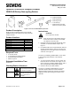
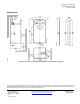
Figure 8. Attaching the Mounting Bracket.
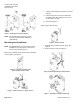
Manual Override
To move the damper blades and lock the position with
no power present, do the following:
1. Slide the red manual override knob toward the
back of the actuator. See figure 9.
2. Make adjustments to the damper position.
3. Slide the red manual override knob toward the
front of the actuator.
Once power is restored, the actuator returns to
automated control.
Figure 9. Manual Override.
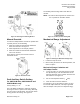
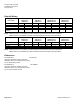
Dual Auxiliary Switch Setting
For GDE/GLB 136x, GDE/GLB164x and
GDE/GLB166x only.
Factory setting: A = 5° B = 85°
Use a flat-blade screwdriver to adjust the A switch.
The long arm of the † points to the setting. Manually
turn the red ring of the B switch. The narrower tab on
the ring points to the setting. See Figure 10.
The auxiliary switch setting shafts rotate with the
actuator.
NOTE: The scale is valid only when the actuator is in
the "0" position on clockwise motion.
Figure 10. Auxiliary Switch Setting Dial.
Mechanical Range Adjustment
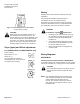
Figure 11. Moving the Mechanical Range Stop.
1. Loosen the stop set screw.
2. Move it along the track to the desired position, and
fasten it in place.
Mechanical Range Limitation and
Self–adapt Feature
1. To use the entire 0 to 10V input signal to control
the adjusted range, raise the tab located on the
lower left-hand side of the actuator and locate the
DIP switches. See Figure 12.
2. Set the self-adapt DIP switch to (ON).
3. Close the tab over the DIP switches.
For example, if you set the locking screw at 70° and
turn the self-adapt switch ON, a 5V input signal will
drive the damper to 35° (50% of its adjusted range).
1
2