
Data Sheet for Product


OpenAir® Non-Spring Return Rotary Electric Damper Actuator Technical Instructions
24 Vac – Modulating Control Document Number 155-187P25
May 13, 2021
Siemens Industry, Inc. Page 15
Wiring, Continued
Post Header AMP
The input cable (purchased separately) brings power and a control signal to the first
actuator in a daisy chain configuration. See Figure 30 and Figure 31.
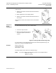
CAUTION:
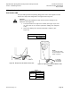
Insert the plug into the GDE161.1N from the left to prevent damage to the
cable wires. (See Figure 29)
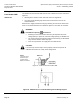
1. The open bracket to the right of the actuator (See Figure 27) is used
for strain relief of the customer purchased cabling (See Required
Tools).
2. Secure the cabling to the actuator bracket with a cable tie. (See
Figure 30.)
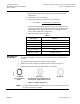
Modulating Control Input Cable
985-133
3 ft
12 pk
Figure 29. Always Insert the Cable From the Left.
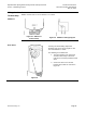
Figure 30. Input Cable Installed in Bottom Three
Contacts.
Table 5.
Daisy Chain Cables
985-134
12 ft
12 pk
985-135
25 ft
12 pk
NOTE:
You must select either
the top 3 contacts or the
bottom 3 contacts.