
Data Sheet for Product


Technical Instructions OpenAir® Non-Spring Return Rotary Electric Damper Actuator
Document Number 155-187P25 24 Vac – Modulating Control
May 13, 2021
Page 12 Siemens Industry, Inc.
Wiring
• All wiring must conform to NEC and local codes and regulations.
• Use earth ground isolating step-down Class 2 transformers. Do not use autotransformers.
• The sum of the VA ratings of all actuators and all other components powered by one
transformer must not exceed the rating of the transformer.
• It is recommended that one transformer power no more than 10 actuators.
WARNING:
All six outputs of the dual auxiliary switch (A and B) must only be connected to:
• Class 2 voltage (UL/CSA).
• Separated Extra-Low Voltage (SELV) or Protective Extra Low Voltage
(PELV) (according to HD384-4-41) for installations requiring
conformance.
WARNINGS:
Installations requiring Conformance:
• All wiring for CE certified actuators must be SELV or PELV rated per
HD384-4-41.
• Use safety-isolating transformers (Class III transformer) per EN61558.
They must be rated for 100% duty cycle.
• Over current protection for supply lines is maximum 10A.
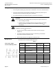
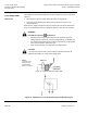
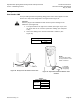
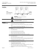
Wiring Diagrams
Each wire has the standard symbol printed on it.
Table 4.
24 Vac power supply
0 to 10V modulating control
Standard
Symbol
Function
Terminal
Designation
Color
1
Supply (SP)
G
Red
2
Neutral (SN)
G0
Black
8
0 to 10V input signal
Y
Gray
9
Output for 0 to 10 Vdc
position indication
U
Pink
Factory-installed Options
S1
Switch A Common
Q11
Gray/Red
S2
Switch A - NC
Q12
Gray/Blue
S3
Switch A - NO
Q14
Gray/Pink
S4
Switch B - Common
Q21
Black/Red
S5
Switch B - NC
Q22
Black/Blue
S6
Switch B - NO
Q24
Black/Pink