
User Manual

A5E03734994A DS02 Seite 4 von 4 page 4 of 4
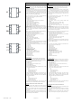
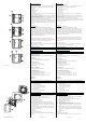
Bild / Figure 4
Bild / Figure 5
Technical Support
℡ +49 (911) 895 - 7222
+49 (911) 895 - 7223
support.automation@siemens.com
http://support.automation.siemens.com
Inbetriebnahme
Allgemeine Beschreibung
Der Taster wird zusammen mit dem zugehörigen Rahmen
(DELTA line / vita / miro) (F3) auf den Busankoppler (BTM) (F1)
gesteckt.
Der Busankoppler (BTM) UP 117 (F1) ist in der UP-Dose
angeschlossen und befestigt (siehe Montageanleitung
Busankoppler (BTM) UP 117).
Busankoppler (BTM) und der zugehörige Rahmen "DELTA line",
„DELTA vita“ oder "DELTA miro" sind nicht im Lieferumfang ent-
halten, sondern müssen separat bestellt werden (siehe gültiger
Katalog).
Montage
− Entfernen Sie den Klarsichtrahmen mit den Tasten (F6) vom
Tastergrundmodul (F5), indem Sie diesen von der Seite her
an den Aussparungen für den Schraubendreher abheben.
− Stecken Sie das Tastergrundmodul (F5) mit dem zugehörigen
Rahmen (F3) auf den Busankoppler (BTM) (F1).
Dabei wird die elektrische Verbindung zwischen dem Taster
und dem Busankoppler (BTM) über das Bus Transceiver Inter-
face (BTI) (F2 und F4) hergestellt.
− Zur Diebstahlsicherung befestigen Sie das Tastergrundmodul
mit den mitgelieferten Schrauben (F7) an dem Busankoppler
(BTM). Diese sind vollständig anzuschrauben. Schnappen Sie
den Klarsichtrahmen mit den Tasten wieder auf.
Demontage
− Entfernen Sie den Klarsichtrahmen mit den Tasten (F6) vom
Tastergrundmodul (F5), indem Sie diesen von der Seite her
an den Aussparungen (F12) für den Schraubendreher abhe-
ben (Bild 4).
− Lösen Sie die Schrauben (F7), mit denen das Tastergrundmo-
dul zur Diebstahlsicherung an dem Busankoppler (BTM) (F1)
befestigt ist.
− Entfernen Sie das Tastergrundmodul (F5) mit dem zugehöri-
gen Rahmen (F3) vom Busankoppler (BTM).
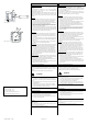
Beschriftung
− Zur Beschriftung heben Sie den Klarsichtrahmen mit den Tas-
ten (F6) ab (Bild 4). Entnehmen Sie die Beschriftungshinter-
grund (F8) dem Klarsichtrahmen (F6). Verwenden Sie ein
transparentes Beschriftungsmedium (z.B. Avery Zweckform
No. J4720 für Tintenstrahldrucker oder Avery Zweckform
No. L4770 für Laserdrucker), das Sie mit dem Beschriftungs-
hintergrund (F8) wieder in den Klarsichtrahmen (F6) einle-
gen. Schnappen Sie den Klarsichtrahmen wieder auf das Tas-
tergrundmodul (F5) auf.
Adresszuweisung
− Entfernen Sie den Klarsichtrahmen mit den Tasten (F6) vom
Grundmodul (F5), indem Sie diesen von der Seite her an den
Aussparungen für den Schraubendreher abheben.
− Betätigen Sie zur Vergabe der physikalischen Adresse die In-
betriebnahmetaste (F9) am Gerät.
- Die Inbetriebnahme LED (F10) leuchtet auf und erlischt nach
Übernahme der physikalischen Adresse.
Drücken der Programmiertaste
<2 s: Programmiermodus für Inbetriebnahme mit ETS.
>2 s …. <20 s: Sondermodus für Desigo TRA. Das Gerät kann
dadurch für den KNX Programmiermodus für ca. 10 s gesperrt
sein. Dies wird durch kurzes Blinken der Programmier – LED an-
gezeigt.
>20 s: Rücksetzen des Gerätes in den Auslieferzustand.
V
WARNUNG
• Das Gerät darf nur von einer zugelassenen Elektrofachkraft
installiert und in Betrieb genommen werden.
• Das Gerät darf in Schaltersteckdosenkombinationen einge-
setzt werden, wenn VDE zugelassene Geräte verwendet wer-
den.
• Die geltenden Sicherheits- und Unfallverhütungsvorschriften
sind zu beachten.
• Bei der Planung und Errichtung von elektrischen Anlagen
sind die einschlägigen Richtlinien, Vorschriften und Bestim-
mungen des jeweiligen Landes zu beachten.
Allgemeine Hinweise
• Die Bedienungsanleitung ist dem Kunden auszuhändigen.
• Ein defektes Gerät ist mit einem Rücklieferschein der zustän-
digen Vertriebsniederlassung zurückzusenden.
• Bei zusätzlichen Fragen zum Produkt wenden Sie sich bitte
an unseren Technical Support.
Hinweis:
Dieses Produkt unterstützt zwei verschiedene Betriebsmodi:
KNX und PL-Link.
Dieses Dokument beschreibt den KNX Funktionsumfang, der mit
der ETS konfiguriert werden kann.
Für PL-Link siehe Dokumentation zu Desigo.
Commissioning
General description
The wall switch is slid onto the bus coupling unit (BTM) (F1) to-
gether with its design frame (DELTA line / vita / miro) (F3).
The bus coupling unit (BTM) UP 117 (F1) is already mounted
into a flush-mount box (see installation instruction of the bus
coupling unit (BTM) UP 117).
Bus coupling unit (BTM) and the design frame “DELTA line”,
“DELTA vita”, or “DELTA miro” are not included and therefore
have to be ordered separately (see current catalog).
Mounting
− Remove the transparent frame with the buttons (F6) from
the wall switch's main module (F5) by inserting a screwdriver
laterally into the recesses and lifting the transparent frame
upwards from the main module.
− Slip the wall switch's main module (F5) together with the de-
sign frame (F3) onto the bus coupling unit (BTM) (F1).
The electrical connection between the wall switch and the
bus coupling unit (BTM) is established via a Bus Transceiver
Interface (BTI) (F2 and F4).
− Securely attach the wall switch's main module to the bus cou-
pling unit (BTM) with the screws (F7) delivered in the pack-
age. Slip the transparent frame with the buttons back onto
the main module.
Unmounting
− Remove the transparent frame with the switch buttons (F6)
from the wall switch's main module (F5) by inserting a screw-
driver laterally into the recesses and lifting the transparent
frame upwards from the main module (figure 4).
− Loosen the screws (F7) securing the wall switch's main mod-
ule to the bus coupling unit (BTM) (F1).
− Remove the wall switch's main module (F5) together with the
design frame (F3) from the bus coupling unit (BTM).
Labeling
− To insert a label remove the transparent frame with the
switch buttons (F6) from the main module (F5) (figure 4).
Separate the white label holder (F8) from the transparent
frame (F6). Label a transparent plastic labeling medium (e.g.
Avery Zweckform No. J4720 for inkjet printers or Avery
Zweckform No. L4770 for laser printers) that you insert into
the transparent frame (F6) with the white label holder (F8).
Slide the transparent frame back onto the main module (F5).
Address assignment
− Remove the transparent frame with the switch buttons (F6)
from the base module (F5) by inserting a screwdriver later-
ally into the recesses and lifting the transparent frame up-
wards from the base module.
− Press the learning button (F9) on the device to initiate the as-
signment of the physical address to the device.
− The programming LED (F10) turns on to indicate the pro-
gramming mode. Upon receiving the physical address the de
− vice automatically returns to normal operating mode and the
LED turns off.
Pressing the programming button
<2 s: Programming mode for commissioning with ETS
>2 s…<20 s: Special mode for Desigo TRA. The device may be
blocked for the KNX programming mode for approx. 10 s. In
this situation the programming LED flashes briefly.
> 20s: The device is reset to the factory default settings.
V
WARNING
• The device must be mounted and commissioned by an
authorised electrician.
• The device may be mounted in switch and socket combina-
tions if VDE-certified devices are used exclusively.
• The prevailing safety rules must be heeded.
• For planning and construction of electric installations, the
relevant guidelines, regulations and standards of the respec-
tive country are to be considered.
General Notes
• The operating instructions must be handed over to the client.
• Any faulty device is to be sent together with a return delivery
note of the local Siemens office.
• If you have further questions concerning the product please
contact our technical support.
Note:
This product supports two different operation modes: KNX und
PL-Link.
This document describes the KNX functionality that can be con-
figured with ETS.
For PL-Link refer to documentation for Desigo.
F14