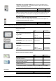
s 9 9222P01 222 Desigo™ PX Automation stations modular series PXC....D PXC...-E.D PXA40-… • Freely programmable modular automation stations for HVAC and building services plants. • Communications – BACnet/IP – BACnet/LonTalk • BTL label (BACnet communications is BTL tested) • Comprehensive management and system functions (alarm management, time schedules, trends, access protection, etc.
Functions Modular, freely programmable automation stations for HVAC and building control systems. • Management functions (alarm management with alarm routing, schedulers, trend functions, remote management, access protection with individually defined user profiles and categories). • For stand-alone applications or for use within a device or system network. • BTL-tested BACnet communications on LonTalk, PTP or IP, compliant with BACnet standard (Rev. 1.12 -for Desigo V6.0 and later) including B-BC profile.
TXM1.. : The flexible range of TX-I/O modules for signaling, measuring, counting, switching, and positioning. The I/O modules with local manual control on the module housing permit the operator to control the equipment manually directly from the cabinet. TX-I/O devices 1) Digital input module 8 or 16 I/O points Universal module without / with local operation and LCD Super universal mod.
PXX-PBUS : The extension module allows connecting installed PTM-I/O modules to PXC50/100/200…D automation stations, making them the perfect solution to migrate legacy systems. PXX-.. device PBUS extension module Type PXX-PBUS Data sheet CM1N9283 Note: One supply module TXS1.12F10 is required as bus supply for the P-bus for each P-bus strand. A TXS1.12F10 can supply max. 64 load units (1 LU = 12.5 mA, DC 24 V) TXA1.
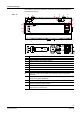
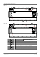
Mechanical design The compact construction enables the automation stations to be mounted on a standard mounting rail. 4 PXC....D 5 8 5 8 5 5 6 3 7 2 5 9222z01 1 8 FW Reset 1 2 3 4 5 6 7 8 9 10 11 12 13 Plastic housing Cover to interface for extension module Front cover or PXM40-W1 option module Plug-in terminal block with screw terminals (operating voltage) Interface for network, operator units, tool, etc.
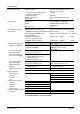
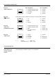
LED indicators Service pin (Desigo) Color Activity Green Continuously ON Continuously OFF Red Continuously OFF FLT Continuously ON Rapid flashing Red Continuously OFF BAT Continuously ON Yello Continuously ON COM w Continuously OFF Flashing Red INF Red Continuously OFF SRV Continuously ON (Ethernet) Function Power OK No power OK Fault Firmware missing / corrupt Battery OK Battery empty– replace! Connection to switch OK No connection to switch Communication Freely programmable OK No connection to switch o
Technical data General device data Operating voltage Safety extra-low voltage SELV or Extra-low voltage PELV Operating frequency Energy consumption Internal fuse Operating data Processor Storage Accuracy class Data backup in event of power failure Communication interfaces AC 24 V ± 20% (SELV / PELV) or AC 24 V class 2 (US) HD 384 50/60 Hz Max. 24 VA (same for all types) 5A Motorola Power PC MPC885 64MB SDRAM / 32MB FLASH (96MB total) 0.
Plug-in screw terminal Power supply, bus, signals Simple cable lengths, cable Connection cable Ethernet and PXM20-E types (see Installation Guide Cable type PX, CA110396) Connection cable LONWORKS bus Cable type Connection cable PXM10 Connection cables for island bus Solid or stranded conductors 0.25…2.5 mm2 or 2 x 1.5 mm2 Max. 100 m Standard at least CAT5 UTP (Unshielded Twisted Pair) or STP (Shielded Twisted Pair) See Installation Guide CA110396 CAT5 Max.
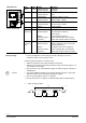
Connection terminals and interfaces 4 5 HMI (C) (B) T (E) HMI / TOOL (A) CLB 1 2 3 24 V~ CLA PXC....D (F) (G) 9222Z10 HMI PXC...-E.
Pin assignment for RJ45 plug Pin description 87654321 1. 2. 3. 4. LONWORKS Data A (CLA) LONWORKS Data B (CLB) G0 / GND G / Plus Pin description 5. 6. 7. 8. Unused Unused Unused Unused 87654321 Plug (E) "HMI / Tool" (LONWORKS and serial) 87654321 9222z12 RJ45 socket screened, standard connection in accordance with AT&T256 9222z12 Plug (D) Ethernet 9222z12 Plug (C) "HMI" (LONWORKS) 87654321 *) 6 9222z12 Plug (G) "HMI" (serial) 1. 2. 3. 4. Tx+ Tx – Rx + Unused 5. 6. 7. 8.
Dimensions All dimensions in mm 74 Automation stations, system controllers PXC….D 192 45 (PXA40-...) 35.5 44 199 66 4 70 81 (PXA40-...) 9222m14 43 90 93 96 4.5 Disposal The device is considered electrical and electronic equipment for disposal in terms of the applicable European Directive and may not be disposed of as domestic garbage. • Dispose of the device through channels provided for this purpose. • Comply with all local and currently applicable laws and regulations.
Issued by: Siemens Switzerland Ltd Smart Infrastructure Global Headquarters Theilerstrasse 1a CH-6300 Zug +41 58 724-2424 www.siemens.com/buildingtechnologies © Siemens Switzerland Ltd 2009 Delivery and technical specifications subject to change 12 / 12 Siemens Smart Infrastructure PXC....D PXC...-E.