
User Manual


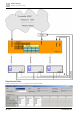


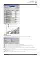

Table Of Contents
- 1 Cyber security disclaimer
- 2 Preconditions of this document
- 3 System overview
- 4 Desigo workflow, tools and programming
- 4.1 Coverage of the technical process
- 4.2 Coverage of the system
- 4.3 Main tasks
- 4.4 Tools for different roles
- 4.5 Working with libraries
- 4.6 Working in parallel and subcontracting
- 4.7 Workflow for primary systems
- 4.8 Workflow for room automation classic
- 4.9 Workflow for Desigo room automation
- 4.10 Desigo Configuration Module (DCM)
- 4.11 Desigo Xworks Plus (XWP)
- 4.12 Desigo Automation Building Tool (ABT)
- 4.13 Programming in D-MAP
- 5 Control concept
- 6 Technical view
- 7 Global objects and functions
- 8 Events and COV reporting
- 9 Alarm management
- 9.1 Alarm sources
- 9.2 Alarm example
- 9.3 Effects of BACnet properties on alarm response
- 9.4 Alarm response of the function blocks
- 9.5 Alarm functions
- 9.6 Alarm management by notification class
- 9.7 Alarm routing over the network
- 9.8 Alarm queuing
- 9.9 Common alarms
- 9.10 Alarm suppression
- 9.11 Alarm message texts
- 10 Calendars and schedulers
- 11 Trending
- 12 Reports
- 13 Data storage
- 14 Network architecture
- 15 Remote access
- 16 Management platform
- 17 Desigo Control Point
- 18 Automation stations
- 19 Logical I/O blocks
- 20 Room automation
- 21 Desigo Open
- 22 System configuration
- 22.1 Technical limits and limit values
- 22.2 Maximum number of elements in a network area
- 22.3 Desigo room automation system function group limits
- 22.4 Devices
- 22.4.1 PXC..D automation stations / system controllers
- 22.4.2 LonWorks system controllers
- 22.4.3 Automation stations with LonWorks integration
- 22.4.4 PX Open integration (PXC001.D/-E.D)
- 22.4.5 PX Open integration (PXC001.D/-E.D + PXA40-RS1)
- 22.4.6 PX Open integration (PXC001.D/-E.D + PXA40-RS2)
- 22.4.7 PX KNX integration (PXC001.D/-E.D)
- 22.4.8 TX Open integration (TXI1/2/2-S.OPEN)
- 22.4.9 Number of data points on Desigo room automation stations
- 22.4.10 Number of data points for PXC3
- 22.4.11 Number of data points for DXR1
- 22.4.12 Number of data points for DXR2
- 22.4.13 PXM20 operator unit
- 22.4.14 PXM10 operator unit
- 22.4.15 Desigo Control Point
- 22.4.16 PXG3.L and PXG3.M BACnet routers
- 22.4.17 SX OPC
- 22.4.18 Desigo CC
- 22.4.19 Desigo Insight
- 22.4.20 Desigo Xworks Plus (XWP)
- 22.4.21 Desigo Automation Building Tool (ABT)
- 22.5 Applications
- 23 Compatibility
- 23.1 Desigo version compatibility definition
- 23.2 Desigo system compatibility basics
- 23.2.1 Compatibility with BACnet standard
- 23.2.2 Compatibility with operating systems
- 23.2.3 Compatibility with SQL servers
- 23.2.4 Compatibility with Microsoft Office
- 23.2.5 Compatibility with web browsers
- 23.2.6 Compatibility with ABT Go
- 23.2.7 Compatibility with VMware (virtual infrastructure)
- 23.2.8 Compatibility of software/libraries on the same PC
- 23.2.9 Hardware and firmware compatibility
- 23.2.10 Backward compatibility
- 23.2.11 Engineering compatibility
- 23.2.12 Compatibility with Desigo Configuration Module (DCM)
- 23.2.13 Compatibility with Desigo PX / Desigo room automation
- 23.2.14 Compatibility with Desigo RX tool
- 23.2.15 Compatibility with TX-I/O
- 23.2.16 Compatibility with TX Open
- 23.3 Desigo Control Point
- 23.4 Upgrading from Desigo V6.2 Update (or Update 2) to V6.2 Update 3
- 23.5 Siemens WEoF clients
- 23.6 Migration compatibility
- 23.7 Hardware requirements of Desigo software products
- 24 Desigo PXC4 and PXC5
- 25 Compatibility of Desigo V6.2 Update 3 with PXC4 and PXC5

Control concept
Superposed plant controls
5
86 | 351 CM110664en_07
On/Off switching of PWR_CTL
When PWR_CTL is switched on [ValPgm = On], the first step in the sequence of the current profile is
executed immediately. In this case, the switch-on delay is not valid. If the trigger for default power is on
[PwrTrg = On], the aggregate is switched directly to the default power level [DefPwr].
A switch-off command [ValPgm = Off], disables all the energy producers defined in the profile table with
Priority 14.
Out of service
If the PWR_CTL function is taken out of service [OoServ = On], then all referenced aggregates are
switched OFF with Priority 14, without taking account of delay times. The monitoring of the aggregates is
disabled.
Demand signals
The current power demand is determined locally in the energy producers. In the event of a power deficit or
surplus, the aggregate will send the appropriate demand signal to the PWR_CTL block. The demand signal
from the aggregate can be generated, e.g., on the basis of the boiler setpoint deviation and the primary
flow. The demand signals of the separate aggregates are combined and transmitted to the [StepUp] or
[StepDn] input of the PWR_CTL block. After expiry of the relevant delay times, the block executes the
appropriate sequence step to increase or reduce the power, as necessary.
When both [StepUp] and [StepDn] demand signals are present simultaneously, [StepDn] takes priority.
Direct switching of a load
In cases where the power is to be increased or decreased without observing the delay times, the default-
power trigger input [PwrTrg] can be used to switch to a defined default power level [DefPwr]. From the
current profile, and taking account of the current power output, the PWR_CTL block determines the
sequence steps required to cover the power demand and implements them directly.
Power display
The block has two outputs at which it displays the current total power of the energy producers. This
consists firstly of the controlled power output [CtldPwr]. This output represents the total power switched
by the PWR_CTL block.
The other output, the present power output [PrPwr], shows the additional power output of energy
producers that are not directly switched by PWR_CTL. To do this, PWR_CTL evaluates the priority array
[PrioArr] of the MVAL blocks. In this way it can detect, e.g., that an energy producer has been switched
manually [Prio8] to a given stage.
Configuration error
The entries in the two configuration tables are checked cyclically for validity.
● A fault alarm is generated under the following circumstances:
● Aggregates no longer accessible from PWR_CTL, owing, e.g., to retrospective modifications to the
technical hierarchy, affecting the references of the energy producers
● Retrospective changes to the stage-limit value in the aggregate, making the value configured in the
profile table too high
● No multistate value object
● Reference block no longer available: e.g., deleted with delta download
● Several references to the same block
● Empty profile table
In the event of a fault alarm, all aggregates still accessible by PWR_CTL are switched OFF permanently.
Alarm management
The PWR_CTL block in the system is an alarm-generating block with a configurable alarm class [AlmCl]
and alarm function [AlmFnct].
An Offnormal process alarm is generated: