
User Manual


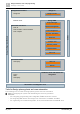


Table Of Contents
- 1 Cyber security disclaimer
- 2 Preconditions of this document
- 3 System overview
- 4 Desigo workflow, tools and programming
- 4.1 Coverage of the technical process
- 4.2 Coverage of the system
- 4.3 Main tasks
- 4.4 Tools for different roles
- 4.5 Working with libraries
- 4.6 Working in parallel and subcontracting
- 4.7 Workflow for primary systems
- 4.8 Workflow for room automation classic
- 4.9 Workflow for Desigo room automation
- 4.10 Desigo Configuration Module (DCM)
- 4.11 Desigo Xworks Plus (XWP)
- 4.12 Desigo Automation Building Tool (ABT)
- 4.13 Programming in D-MAP
- 5 Control concept
- 6 Technical view
- 7 Global objects and functions
- 8 Events and COV reporting
- 9 Alarm management
- 9.1 Alarm sources
- 9.2 Alarm example
- 9.3 Effects of BACnet properties on alarm response
- 9.4 Alarm response of the function blocks
- 9.5 Alarm functions
- 9.6 Alarm management by notification class
- 9.7 Alarm routing over the network
- 9.8 Alarm queuing
- 9.9 Common alarms
- 9.10 Alarm suppression
- 9.11 Alarm message texts
- 10 Calendars and schedulers
- 11 Trending
- 12 Reports
- 13 Data storage
- 14 Network architecture
- 15 Remote access
- 16 Management platform
- 17 Desigo Control Point
- 18 Automation stations
- 19 Logical I/O blocks
- 20 Room automation
- 21 Desigo Open
- 22 System configuration
- 22.1 Technical limits and limit values
- 22.2 Maximum number of elements in a network area
- 22.3 Desigo room automation system function group limits
- 22.4 Devices
- 22.4.1 PXC..D automation stations / system controllers
- 22.4.2 LonWorks system controllers
- 22.4.3 Automation stations with LonWorks integration
- 22.4.4 PX Open integration (PXC001.D/-E.D)
- 22.4.5 PX Open integration (PXC001.D/-E.D + PXA40-RS1)
- 22.4.6 PX Open integration (PXC001.D/-E.D + PXA40-RS2)
- 22.4.7 PX KNX integration (PXC001.D/-E.D)
- 22.4.8 TX Open integration (TXI1/2/2-S.OPEN)
- 22.4.9 Number of data points on Desigo room automation stations
- 22.4.10 Number of data points for PXC3
- 22.4.11 Number of data points for DXR1
- 22.4.12 Number of data points for DXR2
- 22.4.13 PXM20 operator unit
- 22.4.14 PXM10 operator unit
- 22.4.15 Desigo Control Point
- 22.4.16 PXG3.L and PXG3.M BACnet routers
- 22.4.17 SX OPC
- 22.4.18 Desigo CC
- 22.4.19 Desigo Insight
- 22.4.20 Desigo Xworks Plus (XWP)
- 22.4.21 Desigo Automation Building Tool (ABT)
- 22.5 Applications
- 23 Compatibility
- 23.1 Desigo version compatibility definition
- 23.2 Desigo system compatibility basics
- 23.2.1 Compatibility with BACnet standard
- 23.2.2 Compatibility with operating systems
- 23.2.3 Compatibility with SQL servers
- 23.2.4 Compatibility with Microsoft Office
- 23.2.5 Compatibility with web browsers
- 23.2.6 Compatibility with ABT Go
- 23.2.7 Compatibility with VMware (virtual infrastructure)
- 23.2.8 Compatibility of software/libraries on the same PC
- 23.2.9 Hardware and firmware compatibility
- 23.2.10 Backward compatibility
- 23.2.11 Engineering compatibility
- 23.2.12 Compatibility with Desigo Configuration Module (DCM)
- 23.2.13 Compatibility with Desigo PX / Desigo room automation
- 23.2.14 Compatibility with Desigo RX tool
- 23.2.15 Compatibility with TX-I/O
- 23.2.16 Compatibility with TX Open
- 23.3 Desigo Control Point
- 23.4 Upgrading from Desigo V6.2 Update (or Update 2) to V6.2 Update 3
- 23.5 Siemens WEoF clients
- 23.6 Migration compatibility
- 23.7 Hardware requirements of Desigo software products
- 24 Desigo PXC4 and PXC5
- 25 Compatibility of Desigo V6.2 Update 3 with PXC4 and PXC5

Desigo workflow, tools and programming
Main tasks
4
40 | 351 CM110664en_07
programs you develop fit together with all elements in the library and that they are well tested and
documented. You must take care of the compatibility, the versioning and the library packaging.
Creating a technical hierarchy
The technical hierarchy is the BACnet view on the Desigo system. It is based on the plant-related structure
in the building. This hierarchy is defined during engineering. In special cases, if the customer requires it,
the technical hierarchy can be built according to a plant-specific structure defined by the customer (user
designation).
This lets, e.g., the customer view the building in Desigo CC according to this structure:
● Building topology (area, building, floor, plant, plant section, etc.)
● Naming in the system (names according to technical hierarchy, user designation or free designation)
Creating loadable components for the automation stations
The result of the engineering are loadable configurations:
● Configuration of the automation station: Network configuration (IP, LON, MS TP addresses), BACnet
configuration (BACnet name and BACnet ID)
● Application: I/O configuration and setting parameters or program (for programmable automation
stations)
● Operating language: When you load the configuration, the operating language for the generic operation
is also loaded
● Firmware: For system upgrade or bug fixing
Creating the configuration of operation
The system devices can be operated locally, over the web, on a touch panel or in Desigo CC. Operations
can either be generic (without additional engineering) or dedicated (with additional engineering via
favorites or operating graphics).
● The generic operation is based on the technical hierarchy. It must not be engineered.
● The room operation can be configured.
● Favorites are a simple grouping of operable elements in a summarized view. This view can also be
generic, e.g., as a favorite in ABT-SSA, or it can be engineered, e.g., as a favorite for PXM20.
● The graphic operation must be engineered.
Installation, test and commissioning
An I/O configuration must be loaded for the point test. An application program is not always loaded with
the configuration.
You can carry out a point test with an application program if the application program can be turned off
during the point test. This way you can carry out a test if, e.g., a central security function would prohibit you
from operating the I/O, e.g., if a central security function does not allow lowering the blinds.
The test protocol can store which points have passed the test and which points have an error.
Creating local documentation and project documentation
The tools have two types of documentation:
● Local documents (work documents, simple templates, Excel exports) can be used to, e.g., verify results.
You can, e.g., export them to Excel and add additional data to them.
● Project documentation (template with logo, author, table of contents, etc.) can be attached to the
customer documentation either in printed form or as a PDF.
Managing project data
You can manage project data in three ways:
● Local project data management - You can save project data locally, that is, on the local computer or on
a share.
● Project data backup - You can create project data archives to, e.g., locally save the intermediate status
of engineering data.
● Project data on the Branch Office Server (BOS) - You can store project data on a BOS. This allows:
– Data storage on a server, incl. data backup