
User Manual
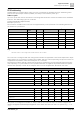


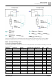


Table Of Contents
- 1 Cyber security disclaimer
- 2 Preconditions of this document
- 3 System overview
- 4 Desigo workflow, tools and programming
- 4.1 Coverage of the technical process
- 4.2 Coverage of the system
- 4.3 Main tasks
- 4.4 Tools for different roles
- 4.5 Working with libraries
- 4.6 Working in parallel and subcontracting
- 4.7 Workflow for primary systems
- 4.8 Workflow for room automation classic
- 4.9 Workflow for Desigo room automation
- 4.10 Desigo Configuration Module (DCM)
- 4.11 Desigo Xworks Plus (XWP)
- 4.12 Desigo Automation Building Tool (ABT)
- 4.13 Programming in D-MAP
- 5 Control concept
- 6 Technical view
- 7 Global objects and functions
- 8 Events and COV reporting
- 9 Alarm management
- 9.1 Alarm sources
- 9.2 Alarm example
- 9.3 Effects of BACnet properties on alarm response
- 9.4 Alarm response of the function blocks
- 9.5 Alarm functions
- 9.6 Alarm management by notification class
- 9.7 Alarm routing over the network
- 9.8 Alarm queuing
- 9.9 Common alarms
- 9.10 Alarm suppression
- 9.11 Alarm message texts
- 10 Calendars and schedulers
- 11 Trending
- 12 Reports
- 13 Data storage
- 14 Network architecture
- 15 Remote access
- 16 Management platform
- 17 Desigo Control Point
- 18 Automation stations
- 19 Logical I/O blocks
- 20 Room automation
- 21 Desigo Open
- 22 System configuration
- 22.1 Technical limits and limit values
- 22.2 Maximum number of elements in a network area
- 22.3 Desigo room automation system function group limits
- 22.4 Devices
- 22.4.1 PXC..D automation stations / system controllers
- 22.4.2 LonWorks system controllers
- 22.4.3 Automation stations with LonWorks integration
- 22.4.4 PX Open integration (PXC001.D/-E.D)
- 22.4.5 PX Open integration (PXC001.D/-E.D + PXA40-RS1)
- 22.4.6 PX Open integration (PXC001.D/-E.D + PXA40-RS2)
- 22.4.7 PX KNX integration (PXC001.D/-E.D)
- 22.4.8 TX Open integration (TXI1/2/2-S.OPEN)
- 22.4.9 Number of data points on Desigo room automation stations
- 22.4.10 Number of data points for PXC3
- 22.4.11 Number of data points for DXR1
- 22.4.12 Number of data points for DXR2
- 22.4.13 PXM20 operator unit
- 22.4.14 PXM10 operator unit
- 22.4.15 Desigo Control Point
- 22.4.16 PXG3.L and PXG3.M BACnet routers
- 22.4.17 SX OPC
- 22.4.18 Desigo CC
- 22.4.19 Desigo Insight
- 22.4.20 Desigo Xworks Plus (XWP)
- 22.4.21 Desigo Automation Building Tool (ABT)
- 22.5 Applications
- 23 Compatibility
- 23.1 Desigo version compatibility definition
- 23.2 Desigo system compatibility basics
- 23.2.1 Compatibility with BACnet standard
- 23.2.2 Compatibility with operating systems
- 23.2.3 Compatibility with SQL servers
- 23.2.4 Compatibility with Microsoft Office
- 23.2.5 Compatibility with web browsers
- 23.2.6 Compatibility with ABT Go
- 23.2.7 Compatibility with VMware (virtual infrastructure)
- 23.2.8 Compatibility of software/libraries on the same PC
- 23.2.9 Hardware and firmware compatibility
- 23.2.10 Backward compatibility
- 23.2.11 Engineering compatibility
- 23.2.12 Compatibility with Desigo Configuration Module (DCM)
- 23.2.13 Compatibility with Desigo PX / Desigo room automation
- 23.2.14 Compatibility with Desigo RX tool
- 23.2.15 Compatibility with TX-I/O
- 23.2.16 Compatibility with TX Open
- 23.3 Desigo Control Point
- 23.4 Upgrading from Desigo V6.2 Update (or Update 2) to V6.2 Update 3
- 23.5 Siemens WEoF clients
- 23.6 Migration compatibility
- 23.7 Hardware requirements of Desigo software products
- 24 Desigo PXC4 and PXC5
- 25 Compatibility of Desigo V6.2 Update 3 with PXC4 and PXC5

Logical I/O blocks
Slope [Slpe] and Intercept [Icpt]
19
CM110664en_07 279 | 351
Solution examples:
Zener diode Voltage divider
Active setpoint adjuster BSG61
(Datasheet CE1N1992)
Slope must be adapted to 0...5 V
(0.01 -> 0.005)
Precision resistance, e.g., VISHAI
MBB/SMA 0207
Switch position 1 (Setpoint limit
control) Setpoint 100%
[Icpt] and [Slpe] for BT devices
Note for all U10 inputs
The physical inputs are designed for 0 -10V with narrow high and low tolerance limits. If a value falls
outside this range, the input transmits an error signal. However, provided it is established that the
peripheral devices are in order, an error signal can be prevented by using a transient voltage suppressor
(10 V Zener diode and two resistors). A faulty response from the analog input signal supplied cannot
subsequently be detected in the automation station.
Example of a circuit including the QAF64 which transmits more than 10 volts
10563A22
U10
U10
0 ... 5 V
U10
BSG61