
User Manual


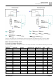


Table Of Contents
- 1 Cyber security disclaimer
- 2 Preconditions of this document
- 3 System overview
- 4 Desigo workflow, tools and programming
- 4.1 Coverage of the technical process
- 4.2 Coverage of the system
- 4.3 Main tasks
- 4.4 Tools for different roles
- 4.5 Working with libraries
- 4.6 Working in parallel and subcontracting
- 4.7 Workflow for primary systems
- 4.8 Workflow for room automation classic
- 4.9 Workflow for Desigo room automation
- 4.10 Desigo Configuration Module (DCM)
- 4.11 Desigo Xworks Plus (XWP)
- 4.12 Desigo Automation Building Tool (ABT)
- 4.13 Programming in D-MAP
- 5 Control concept
- 6 Technical view
- 7 Global objects and functions
- 8 Events and COV reporting
- 9 Alarm management
- 9.1 Alarm sources
- 9.2 Alarm example
- 9.3 Effects of BACnet properties on alarm response
- 9.4 Alarm response of the function blocks
- 9.5 Alarm functions
- 9.6 Alarm management by notification class
- 9.7 Alarm routing over the network
- 9.8 Alarm queuing
- 9.9 Common alarms
- 9.10 Alarm suppression
- 9.11 Alarm message texts
- 10 Calendars and schedulers
- 11 Trending
- 12 Reports
- 13 Data storage
- 14 Network architecture
- 15 Remote access
- 16 Management platform
- 17 Desigo Control Point
- 18 Automation stations
- 19 Logical I/O blocks
- 20 Room automation
- 21 Desigo Open
- 22 System configuration
- 22.1 Technical limits and limit values
- 22.2 Maximum number of elements in a network area
- 22.3 Desigo room automation system function group limits
- 22.4 Devices
- 22.4.1 PXC..D automation stations / system controllers
- 22.4.2 LonWorks system controllers
- 22.4.3 Automation stations with LonWorks integration
- 22.4.4 PX Open integration (PXC001.D/-E.D)
- 22.4.5 PX Open integration (PXC001.D/-E.D + PXA40-RS1)
- 22.4.6 PX Open integration (PXC001.D/-E.D + PXA40-RS2)
- 22.4.7 PX KNX integration (PXC001.D/-E.D)
- 22.4.8 TX Open integration (TXI1/2/2-S.OPEN)
- 22.4.9 Number of data points on Desigo room automation stations
- 22.4.10 Number of data points for PXC3
- 22.4.11 Number of data points for DXR1
- 22.4.12 Number of data points for DXR2
- 22.4.13 PXM20 operator unit
- 22.4.14 PXM10 operator unit
- 22.4.15 Desigo Control Point
- 22.4.16 PXG3.L and PXG3.M BACnet routers
- 22.4.17 SX OPC
- 22.4.18 Desigo CC
- 22.4.19 Desigo Insight
- 22.4.20 Desigo Xworks Plus (XWP)
- 22.4.21 Desigo Automation Building Tool (ABT)
- 22.5 Applications
- 23 Compatibility
- 23.1 Desigo version compatibility definition
- 23.2 Desigo system compatibility basics
- 23.2.1 Compatibility with BACnet standard
- 23.2.2 Compatibility with operating systems
- 23.2.3 Compatibility with SQL servers
- 23.2.4 Compatibility with Microsoft Office
- 23.2.5 Compatibility with web browsers
- 23.2.6 Compatibility with ABT Go
- 23.2.7 Compatibility with VMware (virtual infrastructure)
- 23.2.8 Compatibility of software/libraries on the same PC
- 23.2.9 Hardware and firmware compatibility
- 23.2.10 Backward compatibility
- 23.2.11 Engineering compatibility
- 23.2.12 Compatibility with Desigo Configuration Module (DCM)
- 23.2.13 Compatibility with Desigo PX / Desigo room automation
- 23.2.14 Compatibility with Desigo RX tool
- 23.2.15 Compatibility with TX-I/O
- 23.2.16 Compatibility with TX Open
- 23.3 Desigo Control Point
- 23.4 Upgrading from Desigo V6.2 Update (or Update 2) to V6.2 Update 3
- 23.5 Siemens WEoF clients
- 23.6 Migration compatibility
- 23.7 Hardware requirements of Desigo software products
- 24 Desigo PXC4 and PXC5
- 25 Compatibility of Desigo V6.2 Update 3 with PXC4 and PXC5

Logical I/O blocks
Slope [Slpe] and Intercept [Icpt]
19
276 | 351 CM110664en_07
Signal type
measurement
Description Standard
measuring range
Resolution on the
bus
Value range on
the bus
[Slpe] [Icpt]
I25/020 (Shunt 100
Ohm)
DC 0 ... 25mA 0 … 10 mA 1/500 V 0 ... 5000 0.002 0
I25/020 (Shunt 50
Ohm)
DC 0 ... 25mA 0 … 20 mA 1/250 V 0 ... 5000 0.004 0
I25/020 (Shunt 40
Ohm)
DC 0 ... 25mA 0 … 25 mA 1/200 V 0 ... 5000 0.005 0
I25/020 TX-I/O* DC 0 ... 20mA*) 0 ... 20 mA* 1/1000 mA 0 ... 20000 0.001* 0
U10 (Shunt 400
Ohm) TX-I/O*
DC 0 ... 25mA*) 0 ... 25 mA* 1/1000 V 0 ... 10000 0.0025* 0
Key
*
TX-I/O modules support only 0 ... 20 mA. For a range of 0 ... 25 mA, use the shunt for 400 Ohm (0.1%, 1 W) and measure the
voltage with U10.
I/O configuration PX Compact
The analog input block is used in the Desigo PX Compact PXC10 TL to PXC52 automation station in cases
where an LG Ni1000 sensor (signal type R1K) or DC 0…10 V (U10) is connected to device terminals
X1…X16 of Module 001.
The following information results:
Signal type measurement Description Standard measuring range [Slpe] [Icpt]
R1K LG-Ni 1000 -50…150 °C 0.01 0
U10 DC 0…10V 0…10 Volt 0.001 0
BACnet referencing
Reference to a value in another BACnet object. As the referenced value is already available as a converted
or resulting value, no conversion is required, that is, [Slpe] must be defined as 1 and [Icpt] as 0.
PPS2 interface
The measured value from a room unit connected via the PPS2 interface. In the analog input block, only
Objects 24 (setpoint correction) and 40 (room temperature) may be used. As the value is already available
as a converted or referenced value, no conversion is required, that is, [Slpe] must be defined as 1 and
[Icpt] as 0.
[Slpe] and [Icpt] Analog Output
I/O modules PX modular
In the PX modular automation stations, the analog output block is used with the following signal types:
Signal type positioning Description Standard measuring range [Slpe] [Icpt]
Y10S DC 0…10 V 0 … 10 V 100 0
Y420 DC 4…20 mA 4 … 20 mA 160 4000
Y250T (P-bus)* Three-point AC 24…250 Volt 2.55* 0
Y250T (Island bus)* Three-point AC 24…250 Volt 100* 0
Key
*
Value [Slpe] for Y250T is not a physical value, but rather a special code controlling output of the AO to two relay outputs. This
code differs between P-bus and island bus.
I/O configuration PX Compact
The analog output block is used in the PX compact automation stations, when valves or actuators with DC
0…10 V control signals, signal type Y10S, are connected to device terminals Y1…Y8 of Module 004.