
User's Guide
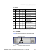
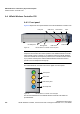


Table Of Contents
- 1 About this Guide
- Contents
- 2 Overview of the HiPath Wireless Controller, Access Points and Convergence Software solution
- 2.1 Conventional wireless LANs
- 2.2 Elements of the HiPath Wireless Controller, Access Points and Convergence Software solution
- 2.3 HiPath Wireless Controller, Access Points and Convergence Software and your network
- 2.4 HiPath Wireless Controller product family
- 3 Configuring the HiPath Wireless Controller
- 3.1 System configuration overview
- 3.2 Logging on to the HiPath Wireless Controller
- 3.3 Working with the basic installation wizard
- 3.4 Configuring the HiPath Wireless Controller for the first time
- 3.4.1 Changing the administrator password
- 3.4.2 Applying product license keys
- 3.4.3 Setting up the data ports
- 3.4.4 Setting up Internal VLAN ID and multi-cast support
- 3.4.5 Setting up static routes
- 3.4.6 Setting up OSPF Routing
- 3.4.7 Configuring filtering at the interface level
- 3.4.8 Installing certificates on the HiPath Wireless Controller
- 3.4.9 Configuring the login authentication mode
- 3.4.10 Configuring network time
- 3.4.11 Configuring DNS servers for resolving host names of RADIUS servers
- 3.5 Additional ongoing operations of the system
- 4 Configuring the Wireless AP
- 4.1 Wireless AP overview
- 4.2 Discovery and registration overview
- 4.2.1 Wireless AP discovery
- 4.2.2 Registration after discovery
- 4.2.3 Understanding the Wireless AP LED status
- 4.2.4 Configuring the Wireless APs for the first time
- 4.2.5 Defining properties for the discovery process
- 4.2.6 Connecting the Wireless AP to a power source and initiating the discovery and registration process
- 4.3 Adding and registering a Wireless AP manually
- 4.4 Configuring Wireless AP settings
- 4.4.1 Modifying a Wireless AP’s status
- 4.4.2 Configuring a Wireless AP’s properties
- 4.4.3 AP properties tab configuration
- 4.4.4 Assigning Wireless AP radios to a VNS
- 4.4.5 Configuring Wireless AP radio properties
- 4.4.6 Setting up the Wireless AP using static configuration
- 4.4.7 Configuring Telnet/SSH Access
- 4.5 Configuring VLAN tags for Wireless APs
- 4.6 Modifying a Wireless AP’s properties based on a default AP configuration
- 4.7 Modifying the Wireless AP’s default setting using the Copy to Defaults feature
- 4.8 Configuring Wireless APs simultaneously
- 4.9 Configuring an AP as a sensor
- 4.10 Performing Wireless AP software maintenance
- 5 Virtual Network Services concepts
- 6 Configuring a VNS
- 6.1 High level VNS configuration flow
- 6.2 VNS global settings
- 6.2.1 Defining RADIUS servers and MAC address format
- 6.2.2 Configuring Dynamic Authorization Server support
- 6.2.3 Defining Wireless QoS Admission Control Thresholds
- 6.2.4 Defining Wireless QoS Flexible Client Access
- 6.2.5 Working with bandwidth control profiles
- 6.2.6 Configuring the Global Default Policy
- 6.2.7 Using the Sync Summary
- 6.3 Methods for configuring a VNS
- 6.4 Working with the VNS wizard to create a new VNS
- 6.5 Working with a GuestPortal VNS
- 6.6 Creating a VNS using the advanced method
- 6.7 Working with existing VNSs
- 6.8 Configuring a Topology
- 6.9 Configuring WLAN Services
- 6.9.1 Configuring a WLAN Service
- 6.9.2 Configuring privacy
- 6.9.3 Configuring accounting and authentication
- 6.9.3.1 Vendor Specific Attributes
- 6.9.3.2 Defining accounting methods for a WLAN Service
- 6.9.3.3 Configuring authentication for a WLAN Service
- 6.9.3.4 Defining the RADIUS server priority for RADIUS redundancy
- 6.9.3.5 Configuring assigned RADIUS servers
- 6.9.3.6 Defining a WLAN Service with no authentication
- 6.9.3.7 Configuring Captive Portal for internal or external authentication
- 6.9.4 Configuring the QoS policy
- 6.10 Configuring Policy
- 6.11 Working with a Wireless Distribution System
- 6.11.1 Simple WDS configuration
- 6.11.2 Wireless Repeater configuration
- 6.11.3 Wireless Bridge configuration
- 6.11.4 Examples of deployment
- 6.11.5 WDS WLAN Services
- 6.11.6 Key features of WDS
- 6.11.7 Deploying the WDS system
- 6.11.7.1 Connecting the WDS Wireless APs to the enterprise network for discovery and registration
- 6.11.7.2 Configuring the WDS Wireless APs through the HiPath Wireless Controller
- 6.11.7.3 Assigning the Satellite Wireless APs’ radios to the network WLAN Services
- 6.11.7.4 Connecting the WDS Wireless APs to the enterprise network for provisioning
- 6.11.7.5 Moving the WDS Wireless APs to the target location
- 6.11.8 Changing the pre-shared key in a WDS WLAN Service
- 7 Availability and session availability
- 8 Configuring Mobility
- 9 Working with third-party APs
- 10 Working with the Mitigator
- 11 Working with reports and displays
- 12 Performing system administration
- 13 Glossary
- A HiPath Wireless Controller’s physical description
- B Regulatory information
- C optiPoint WL2 Configuration
- D SpectraLink Wireless Telephones
- E Default GuestPortal source code
- 2 Overview of the HiPath Wireless Controller, Access Points and Convergence Software solution

hwc_appendixa.fm
HiPath Wireless Controller’s physical description
HiPath Wireless Controller C20
9034530-02,
March 2010
HiPath Wireless Controller, Access Points and Convergence Software V7.11, User Guide 493
• ACTIVITY LED – Indicates the CPU activity, including the amount of traffic
carried to and from the Wireless APs.
• STATUS LED – Indicates the normal state of the HiPath Wireless Controller
as seen by the system’s software. This LED covers all stages of the HiPath
Wireless Controller, ranging from restarting to shutting-down. As long as the
HiPath Wireless Controller is running normally, this LED will remain lit.
Note: When the system configuration is in progress, the Activity and Status
LEDs are set to Amber and blink on a two-second interval.
• HDD Activity LED – Reports Hard Drive Device (HDD) activity.
• Hot Swap LED – Indicates that the hot swap lever on the HiPath Wireless
Controller is pulled out.
A.4.2 LED states
The description of the HiPath Wireless Controller C20 LED status and activity
states is provided below.
• LED 3 – HDD Activity LED – Orange/Amber
• HDD Activity LED is off when HDD is not in use
• HDD Activity LED is on when HDD is in use
• LED 4 – Hot Swap LED – Blue
Status LED Activity LED Condition
Blinking Amber Green Power up (BIOS, POST)
Blinking Amber (2
second rate)
Blinking Amber (2
second rate)
System configuration in progress
Off Green System booting (failed to boot)
Off Green Start up manager: task started
Solid Green Blinking Green Start up manager: task completes startup – all
components active
Solid Amber Blinking Green A component fails to start or needs restarting.
(startup manager task retrying that component)
Green Blinking Red Possible hardware failure (no more retries)
Solid Red Off A component fails (no more retries)
Blinking Red Off System about to reset by watchdog
Solid Red Solid Red System shutdown / halt (requires a manual
reboot)
Table 42 HiPath Wireless Controller C20 LED states and their description