
User's Guide


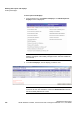


Table Of Contents
- 1 About this Guide
- Contents
- 2 Overview of the HiPath Wireless Controller, Access Points and Convergence Software solution
- 2.1 Conventional wireless LANs
- 2.2 Elements of the HiPath Wireless Controller, Access Points and Convergence Software solution
- 2.3 HiPath Wireless Controller, Access Points and Convergence Software and your network
- 2.4 HiPath Wireless Controller product family
- 3 Configuring the HiPath Wireless Controller
- 3.1 System configuration overview
- 3.2 Logging on to the HiPath Wireless Controller
- 3.3 Working with the basic installation wizard
- 3.4 Configuring the HiPath Wireless Controller for the first time
- 3.4.1 Changing the administrator password
- 3.4.2 Applying product license keys
- 3.4.3 Setting up the data ports
- 3.4.4 Setting up Internal VLAN ID and multi-cast support
- 3.4.5 Setting up static routes
- 3.4.6 Setting up OSPF Routing
- 3.4.7 Configuring filtering at the interface level
- 3.4.8 Installing certificates on the HiPath Wireless Controller
- 3.4.9 Configuring the login authentication mode
- 3.4.10 Configuring network time
- 3.4.11 Configuring DNS servers for resolving host names of RADIUS servers
- 3.5 Additional ongoing operations of the system
- 4 Configuring the Wireless AP
- 4.1 Wireless AP overview
- 4.2 Discovery and registration overview
- 4.2.1 Wireless AP discovery
- 4.2.2 Registration after discovery
- 4.2.3 Understanding the Wireless AP LED status
- 4.2.4 Configuring the Wireless APs for the first time
- 4.2.5 Defining properties for the discovery process
- 4.2.6 Connecting the Wireless AP to a power source and initiating the discovery and registration process
- 4.3 Adding and registering a Wireless AP manually
- 4.4 Configuring Wireless AP settings
- 4.4.1 Modifying a Wireless AP’s status
- 4.4.2 Configuring a Wireless AP’s properties
- 4.4.3 AP properties tab configuration
- 4.4.4 Assigning Wireless AP radios to a VNS
- 4.4.5 Configuring Wireless AP radio properties
- 4.4.6 Setting up the Wireless AP using static configuration
- 4.4.7 Configuring Telnet/SSH Access
- 4.5 Configuring VLAN tags for Wireless APs
- 4.6 Modifying a Wireless AP’s properties based on a default AP configuration
- 4.7 Modifying the Wireless AP’s default setting using the Copy to Defaults feature
- 4.8 Configuring Wireless APs simultaneously
- 4.9 Configuring an AP as a sensor
- 4.10 Performing Wireless AP software maintenance
- 5 Virtual Network Services concepts
- 6 Configuring a VNS
- 6.1 High level VNS configuration flow
- 6.2 VNS global settings
- 6.2.1 Defining RADIUS servers and MAC address format
- 6.2.2 Configuring Dynamic Authorization Server support
- 6.2.3 Defining Wireless QoS Admission Control Thresholds
- 6.2.4 Defining Wireless QoS Flexible Client Access
- 6.2.5 Working with bandwidth control profiles
- 6.2.6 Configuring the Global Default Policy
- 6.2.7 Using the Sync Summary
- 6.3 Methods for configuring a VNS
- 6.4 Working with the VNS wizard to create a new VNS
- 6.5 Working with a GuestPortal VNS
- 6.6 Creating a VNS using the advanced method
- 6.7 Working with existing VNSs
- 6.8 Configuring a Topology
- 6.9 Configuring WLAN Services
- 6.9.1 Configuring a WLAN Service
- 6.9.2 Configuring privacy
- 6.9.3 Configuring accounting and authentication
- 6.9.3.1 Vendor Specific Attributes
- 6.9.3.2 Defining accounting methods for a WLAN Service
- 6.9.3.3 Configuring authentication for a WLAN Service
- 6.9.3.4 Defining the RADIUS server priority for RADIUS redundancy
- 6.9.3.5 Configuring assigned RADIUS servers
- 6.9.3.6 Defining a WLAN Service with no authentication
- 6.9.3.7 Configuring Captive Portal for internal or external authentication
- 6.9.4 Configuring the QoS policy
- 6.10 Configuring Policy
- 6.11 Working with a Wireless Distribution System
- 6.11.1 Simple WDS configuration
- 6.11.2 Wireless Repeater configuration
- 6.11.3 Wireless Bridge configuration
- 6.11.4 Examples of deployment
- 6.11.5 WDS WLAN Services
- 6.11.6 Key features of WDS
- 6.11.7 Deploying the WDS system
- 6.11.7.1 Connecting the WDS Wireless APs to the enterprise network for discovery and registration
- 6.11.7.2 Configuring the WDS Wireless APs through the HiPath Wireless Controller
- 6.11.7.3 Assigning the Satellite Wireless APs’ radios to the network WLAN Services
- 6.11.7.4 Connecting the WDS Wireless APs to the enterprise network for provisioning
- 6.11.7.5 Moving the WDS Wireless APs to the target location
- 6.11.8 Changing the pre-shared key in a WDS WLAN Service
- 7 Availability and session availability
- 8 Configuring Mobility
- 9 Working with third-party APs
- 10 Working with the Mitigator
- 11 Working with reports and displays
- 12 Performing system administration
- 13 Glossary
- A HiPath Wireless Controller’s physical description
- B Regulatory information
- C optiPoint WL2 Configuration
- D SpectraLink Wireless Telephones
- E Default GuestPortal source code
- 2 Overview of the HiPath Wireless Controller, Access Points and Convergence Software solution

hwc_mitigator.fm
Working with the Mitigator
Viewing the Scanner Status report
9034530-02,
March 2010
HiPath Wireless Controller, Access Points and Convergence Software V7.11, User Guide 425
4. To delete the selected APs, click Delete marked APs.
Note: The selected APs are deleted from the Mitigator database, not from the
HiPath Wireless Controller database. You can delete the APs from the HiPath
Wireless Controller database after you delete them from the Wireless AP
Configuration Access Approval screen of the corresponding RF Data
Collector Engine. You can also delete the selected third-party APs if they are
removed from the corresponding VNS in the RF Collector Engine, or if that
VNS has been deleted from the VNS list.
10.8 Viewing the Scanner Status report
When the Mitigator is enabled, you can view a report on the connection status of
the RF Data Collector Engines with the Analysis Engine.
To view the Mitigator scanner engine status display:
1. From the main menu, click Mitigator. The Mitigator screen is displayed.
2. Click the Reports: Scanner Status. The Scanner Status report is displayed.
The boxes display the IP address of the Data Collector engine. The status of the
Data Collector engine is indicated by one of the following colors:
•Green – The Analysis Engine has connection with the Data Collector on that
HiPath Wireless Controller.
• Yellow – The Analysis Engine has connected to the communication system
of the other controller, but has not synchronized with the Data Collector.
Ensure that the Data Collector is running on the remote controller.
•Red – The Analysis Engine is aware of the Data Collector and attempting
connection.