
User's Manual

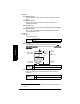
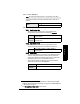
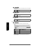
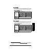
Table Of Contents
- Safety Notes
- FCC Conformity
- CE Electromagnetic Compatibility (EMC) Conformity
- Industry Canada
- The Manual
- Technical Support
- SITRANS LR560 Overview
- Specifications
- Installation
- Wiring
- Local Operation
- Operating via AMS Device Manager
- Functions in AMS Device Manager
- Programming via AMS Device Manager
- Adding a new device
- Startup
- Configuring a new device
- Changing Block Modes
- Configure/Setup Parameters
- Transducer Block Parameters
- Level Transducer Block Parameters
- Operation (LTB)
- Simulation (Input)
- Setup (LTB)
- General
- Calibration
- Rate
- Signal Processing (LTB)
- Range
- Echo Select
- Sampling
- Echo Quality
- Filtering
- TVT Setup
- TVT Shaper 1
- TVT Shaper 2
- TVT Shaper 3
- Echo Profile Parameters (view only)
- Maintenance & Diagnostics (LTB)
- Sensor Lifetime
- Service Schedule
- Communication (LTB)
- Communication:
- Configure/Setup (Liquid Crystal Display Block-LCD)
- Configure/Setup (Diagnostic Transducer Block-DIAG)
- Configure/Setup (Resource Block - RESOURCE)
- Device Diagnostics (Level Transducer Block - LTB)
- Device Diagnostics (Level Control Device Block - LCD)
- Device Diagnostics (Diagnostic Transducer Block - DIAG)
- Device Diagnostics (Resource Block - RESOURCE)
- Password Protection
- AMS Menu Structure
- Parameter Reference
- 1. Quick Start
- 2. Setup
- 2.1. Identification
- 2.2. Device
- 2.3. Sensor
- 2.4. Signal Processing
- 2.4.1. Near Range
- 2.4.2. Far Range
- 2.4.3. Minimum Sensor Value
- 2.4.4. Maximum Sensor Value
- 2.4.5. Echo Select
- 2.4.6. Sampling
- 2.4.7. Echo Quality
- 2.4.8. TVT (Auto False Echo Suppression) Setup
- 2.4.9. TVT Shaper
- 2.4.9.1. Shaper 1-9
- 2.4.9.2. Shaper 10-18
- 2.4.9.3. Shaper 19-27
- 2.4.9.4. Shaper 28-36
- 2.4.9.5. Shaper 37-45
- 2.4.9.6. Shaper 46-54
- 2.4.9.7. Shaper 55-63
- 2.4.9.8. Shaper 64-72
- 2.4.9.9. Shaper 73-81
- 2.4.9.10. Shaper 82-90
- 2.4.9.11. Shaper 91-99
- 2.4.9.12. Shaper 100-108
- 2.4.9.13. Shaper 109-117
- 2.4.9.14. Shaper 118-120
- 2.5. AIFB 1
- 2.6. AIFB 2
- 2.7. Measured Values
- 2.8. Filtering
- 3. Diagnostics
- 4. Service
- 5. Communication
- 6. Security
- 7. Language
- Appendix A: Alphabetical Parameter List
- Appendix B: Troubleshooting
- Appendix C: Maintenance
- Appendix D: Technical Reference
- Principles of Operation
- Echo Processing
- Measurement Range
- Measurement Response
- Damping
- Loss of Echo (LOE)
- Temperature derating curves
- Appendix E: Communications
- Appendix F: Firmware Revision History
- Glossary
- Index
- LCD menu structure

7ML19985LY01 SITRANS LR560 (FF) – INSTRUCTION MANUAL Page 93
mmmmm
Parameters
2.3.6.2. Fill Rate/Min
Defines the maximum rate at which the reported sensor value
1)
is allowed
to increase. Allows you to adjust the SITRANS LR560 response to increases
in the actual material level. Fill Rate is automatically updated whenever
Response Rate (2.3.6.1.) is altered.
Enter a value slightly greater than the maximum vessel-filling rate, in units
per minute.
2.3.6.3. Empty rate/Min
Defines the maximum rate at which the reported sensor value
1)
is allowed
to decrease. Adjusts the SITRANS LR560 response to decreases in the
actual material level. Empty Rate is automatically updated whenever
Response Rate (2.3.6.1.) is altered.
Enter a value slightly greater than the vessel’s maximum emptying rate, in
units per minute.
1)
The value produced by the echo processing which represents the distance from sen-
sor reference point to the target (see Minimum Sensor Value (2.4.3.) on page 95 for an
illustration).
Options
Range: 0 to 999 999 m / min.
Response Rate (2.3.6.1.)
Fill Rate
Slow 0.1 m/min (0.32 ft/min)
*
Medium 1.0 m/min (3.28 ft/min)
Fast 10.0 m/min (32.8 ft/min)
Related
parameters
Level Unit (2.3.2.)
Options
Range: 0 to 999 999 m / min.
Response Rate (2.3.6.1.)
Empty Rate
Slow 0.1 m/min (0.32 ft/min)
*
Medium 1.0 m/min (3.28 ft/min)
Fast 10.0 m/min (32.8 ft/min)
Related
parameters
Level Unit (2.3.2.)