
User's Manual

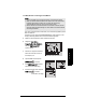
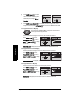
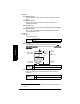
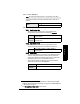
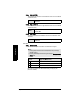
Table Of Contents
- Safety Notes
- FCC Conformity
- CE Electromagnetic Compatibility (EMC) Conformity
- Industry Canada
- The Manual
- Technical Support
- SITRANS LR560 Overview
- Specifications
- Installation
- Wiring
- Local Operation
- Operating via AMS Device Manager
- Functions in AMS Device Manager
- Programming via AMS Device Manager
- Adding a new device
- Startup
- Configuring a new device
- Changing Block Modes
- Configure/Setup Parameters
- Transducer Block Parameters
- Level Transducer Block Parameters
- Operation (LTB)
- Simulation (Input)
- Setup (LTB)
- General
- Calibration
- Rate
- Signal Processing (LTB)
- Range
- Echo Select
- Sampling
- Echo Quality
- Filtering
- TVT Setup
- TVT Shaper 1
- TVT Shaper 2
- TVT Shaper 3
- Echo Profile Parameters (view only)
- Maintenance & Diagnostics (LTB)
- Sensor Lifetime
- Service Schedule
- Communication (LTB)
- Communication:
- Configure/Setup (Liquid Crystal Display Block-LCD)
- Configure/Setup (Diagnostic Transducer Block-DIAG)
- Configure/Setup (Resource Block - RESOURCE)
- Device Diagnostics (Level Transducer Block - LTB)
- Device Diagnostics (Level Control Device Block - LCD)
- Device Diagnostics (Diagnostic Transducer Block - DIAG)
- Device Diagnostics (Resource Block - RESOURCE)
- Password Protection
- AMS Menu Structure
- Parameter Reference
- 1. Quick Start
- 2. Setup
- 2.1. Identification
- 2.2. Device
- 2.3. Sensor
- 2.4. Signal Processing
- 2.4.1. Near Range
- 2.4.2. Far Range
- 2.4.3. Minimum Sensor Value
- 2.4.4. Maximum Sensor Value
- 2.4.5. Echo Select
- 2.4.6. Sampling
- 2.4.7. Echo Quality
- 2.4.8. TVT (Auto False Echo Suppression) Setup
- 2.4.9. TVT Shaper
- 2.4.9.1. Shaper 1-9
- 2.4.9.2. Shaper 10-18
- 2.4.9.3. Shaper 19-27
- 2.4.9.4. Shaper 28-36
- 2.4.9.5. Shaper 37-45
- 2.4.9.6. Shaper 46-54
- 2.4.9.7. Shaper 55-63
- 2.4.9.8. Shaper 64-72
- 2.4.9.9. Shaper 73-81
- 2.4.9.10. Shaper 82-90
- 2.4.9.11. Shaper 91-99
- 2.4.9.12. Shaper 100-108
- 2.4.9.13. Shaper 109-117
- 2.4.9.14. Shaper 118-120
- 2.5. AIFB 1
- 2.6. AIFB 2
- 2.7. Measured Values
- 2.8. Filtering
- 3. Diagnostics
- 4. Service
- 5. Communication
- 6. Security
- 7. Language
- Appendix A: Alphabetical Parameter List
- Appendix B: Troubleshooting
- Appendix C: Maintenance
- Appendix D: Technical Reference
- Principles of Operation
- Echo Processing
- Measurement Range
- Measurement Response
- Damping
- Loss of Echo (LOE)
- Temperature derating curves
- Appendix E: Communications
- Appendix F: Firmware Revision History
- Glossary
- Index
- LCD menu structure

7ML19985LY01 SITRANS LR560 (FF) – INSTRUCTION MANUAL Page 89
mmmmm
Parameters
1.6. Copy Firmware from Display
Transfers firmware from the local display interface to a device.
SW DOWNLOAD is displayed at the beginning of the transfer. This is followed first by
a blank screen (for approximately 2 minutes), then by a progress indicator, and then
by the Siemens logo with the LOE icon. When the transfer is complete,the device
returns to Measurement mode.
2. Setup
2.1. Identification
2.1.1. Tag
Read only. Text that can be used in any way. A recommended use is as a unique
label for a field device in a plant. Limited to 32 ASCII characters.
To access this parameter via AMS Device Manager see Identification under
Identification (RESOURCE) on page 61
.
2.1.2. Descriptor
Read only. Text that can be used in any way. Limited to 32 ASCII characters. No
specific recommended use.
To access this parameter via AMS Device Manager see Identification under
Identification (RESOURCE)
on page 61.
2.1.3. Message
Read only. Text that can be used in any way. Limited to 32 ASCII characters. No
specific recommended use.
To access this parameter via AMS Device Manager see Identification under
Identification (RESOURCE) on page 61
.
2.1.4. Installation date
Read only locally; can be written remotely. The date the device is first
commissioned. (Local display format: YY-MM-DD hh:mm:ss)
Notes:
• See
Local Operation
on page 30 or
Operating via AMS Device Manager
on page 41
for instructions.
• Default settings in the parameter tables are indicated with an asterisk (*) unless
explicitly stated.
• Values shown in the following tables can be entered via the handheld programmer
or local control buttons.
Press RIGHT arrow to Edit.
Press DOWN arrow to select
Start and RIGHT arrow to begin
the transfer.