
User's Manual
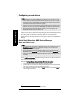

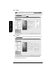
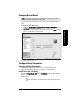
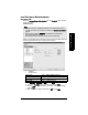
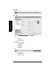
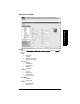
Table Of Contents
- Safety Notes
- FCC Conformity
- CE Electromagnetic Compatibility (EMC) Conformity
- Industry Canada
- The Manual
- Technical Support
- SITRANS LR560 Overview
- Specifications
- Installation
- Wiring
- Local Operation
- Operating via AMS Device Manager
- Functions in AMS Device Manager
- Programming via AMS Device Manager
- Adding a new device
- Startup
- Configuring a new device
- Changing Block Modes
- Configure/Setup Parameters
- Transducer Block Parameters
- Level Transducer Block Parameters
- Operation (LTB)
- Simulation (Input)
- Setup (LTB)
- General
- Calibration
- Rate
- Signal Processing (LTB)
- Range
- Echo Select
- Sampling
- Echo Quality
- Filtering
- TVT Setup
- TVT Shaper 1
- TVT Shaper 2
- TVT Shaper 3
- Echo Profile Parameters (view only)
- Maintenance & Diagnostics (LTB)
- Sensor Lifetime
- Service Schedule
- Communication (LTB)
- Communication:
- Configure/Setup (Liquid Crystal Display Block-LCD)
- Configure/Setup (Diagnostic Transducer Block-DIAG)
- Configure/Setup (Resource Block - RESOURCE)
- Device Diagnostics (Level Transducer Block - LTB)
- Device Diagnostics (Level Control Device Block - LCD)
- Device Diagnostics (Diagnostic Transducer Block - DIAG)
- Device Diagnostics (Resource Block - RESOURCE)
- Password Protection
- AMS Menu Structure
- Parameter Reference
- 1. Quick Start
- 2. Setup
- 2.1. Identification
- 2.2. Device
- 2.3. Sensor
- 2.4. Signal Processing
- 2.4.1. Near Range
- 2.4.2. Far Range
- 2.4.3. Minimum Sensor Value
- 2.4.4. Maximum Sensor Value
- 2.4.5. Echo Select
- 2.4.6. Sampling
- 2.4.7. Echo Quality
- 2.4.8. TVT (Auto False Echo Suppression) Setup
- 2.4.9. TVT Shaper
- 2.4.9.1. Shaper 1-9
- 2.4.9.2. Shaper 10-18
- 2.4.9.3. Shaper 19-27
- 2.4.9.4. Shaper 28-36
- 2.4.9.5. Shaper 37-45
- 2.4.9.6. Shaper 46-54
- 2.4.9.7. Shaper 55-63
- 2.4.9.8. Shaper 64-72
- 2.4.9.9. Shaper 73-81
- 2.4.9.10. Shaper 82-90
- 2.4.9.11. Shaper 91-99
- 2.4.9.12. Shaper 100-108
- 2.4.9.13. Shaper 109-117
- 2.4.9.14. Shaper 118-120
- 2.5. AIFB 1
- 2.6. AIFB 2
- 2.7. Measured Values
- 2.8. Filtering
- 3. Diagnostics
- 4. Service
- 5. Communication
- 6. Security
- 7. Language
- Appendix A: Alphabetical Parameter List
- Appendix B: Troubleshooting
- Appendix C: Maintenance
- Appendix D: Technical Reference
- Principles of Operation
- Echo Processing
- Measurement Range
- Measurement Response
- Damping
- Loss of Echo (LOE)
- Temperature derating curves
- Appendix E: Communications
- Appendix F: Firmware Revision History
- Glossary
- Index
- LCD menu structure

Page 54 SITRANS LR560 (FF) – INSTRUCTION MANUAL 7ML19985LY01
mmmmm
AMS Device Manager
TVT
A custom Time Varying Threshold (TVT) allows you to screen out false echoes, for
example, in a tank with obstructions. See
Auto False Echo Suppression (2.4.8.1.)
on page
142 for more information.
There are two options:
• Auto False Echo Suppression automatically calculates the position of the TVT.
• TVT shaper breakpoints allow you to manually modify the TVT
TVT (Auto False Echo Suppression)
Navigate to Configure/Setup > LTB > Setup > Signal Processing > TVT.
TVT Setup
Click TVT Setup to access:
• Auto False Echo Suppression
For more details see TVT (Auto False Echo Suppression) Setup (2.4.8.) on page
100.
• Auto False Echo Suppression Range
• Hover Level
• Shaper Mode
Allows you to modify breakpoints under the TVT Shaper tabs, and view Manual
TVT-Curve.
1) Turn Shaper Mode On and turn Auto False Echo Suppression Off.
2) Click the appropriate TVT Shaper tab and modify breakpoints as desired.
3) Click Apply.
Notes:
• We recommend using the Auto False Echo Suppression Wizard. See
AFES (Auto
False Echo Suppression) Wizard
on page 87.
• Put LTB Block into OOS Mode before changing settings, then back into AUTO mode
to display TVT.