
User's Manual
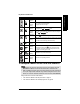
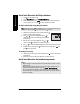

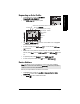
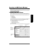
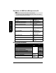
Table Of Contents
- Safety Notes
- FCC Conformity
- CE Electromagnetic Compatibility (EMC) Conformity
- Industry Canada
- The Manual
- Technical Support
- SITRANS LR560 Overview
- Specifications
- Installation
- Wiring
- Local Operation
- Operating via AMS Device Manager
- Functions in AMS Device Manager
- Programming via AMS Device Manager
- Adding a new device
- Startup
- Configuring a new device
- Changing Block Modes
- Configure/Setup Parameters
- Transducer Block Parameters
- Level Transducer Block Parameters
- Operation (LTB)
- Simulation (Input)
- Setup (LTB)
- General
- Calibration
- Rate
- Signal Processing (LTB)
- Range
- Echo Select
- Sampling
- Echo Quality
- Filtering
- TVT Setup
- TVT Shaper 1
- TVT Shaper 2
- TVT Shaper 3
- Echo Profile Parameters (view only)
- Maintenance & Diagnostics (LTB)
- Sensor Lifetime
- Service Schedule
- Communication (LTB)
- Communication:
- Configure/Setup (Liquid Crystal Display Block-LCD)
- Configure/Setup (Diagnostic Transducer Block-DIAG)
- Configure/Setup (Resource Block - RESOURCE)
- Device Diagnostics (Level Transducer Block - LTB)
- Device Diagnostics (Level Control Device Block - LCD)
- Device Diagnostics (Diagnostic Transducer Block - DIAG)
- Device Diagnostics (Resource Block - RESOURCE)
- Password Protection
- AMS Menu Structure
- Parameter Reference
- 1. Quick Start
- 2. Setup
- 2.1. Identification
- 2.2. Device
- 2.3. Sensor
- 2.4. Signal Processing
- 2.4.1. Near Range
- 2.4.2. Far Range
- 2.4.3. Minimum Sensor Value
- 2.4.4. Maximum Sensor Value
- 2.4.5. Echo Select
- 2.4.6. Sampling
- 2.4.7. Echo Quality
- 2.4.8. TVT (Auto False Echo Suppression) Setup
- 2.4.9. TVT Shaper
- 2.4.9.1. Shaper 1-9
- 2.4.9.2. Shaper 10-18
- 2.4.9.3. Shaper 19-27
- 2.4.9.4. Shaper 28-36
- 2.4.9.5. Shaper 37-45
- 2.4.9.6. Shaper 46-54
- 2.4.9.7. Shaper 55-63
- 2.4.9.8. Shaper 64-72
- 2.4.9.9. Shaper 73-81
- 2.4.9.10. Shaper 82-90
- 2.4.9.11. Shaper 91-99
- 2.4.9.12. Shaper 100-108
- 2.4.9.13. Shaper 109-117
- 2.4.9.14. Shaper 118-120
- 2.5. AIFB 1
- 2.6. AIFB 2
- 2.7. Measured Values
- 2.8. Filtering
- 3. Diagnostics
- 4. Service
- 5. Communication
- 6. Security
- 7. Language
- Appendix A: Alphabetical Parameter List
- Appendix B: Troubleshooting
- Appendix C: Maintenance
- Appendix D: Technical Reference
- Principles of Operation
- Echo Processing
- Measurement Range
- Measurement Response
- Damping
- Loss of Echo (LOE)
- Temperature derating curves
- Appendix E: Communications
- Appendix F: Firmware Revision History
- Glossary
- Index
- LCD menu structure

7ML19985LY01 SITRANS LR560 (FF) – OPERATING INSTRUCTIONS Page 35
mmmmm
Quick Start: local
Key functions in Edit mode
To configure a device via the local user interface
Configure the device via the Quick Start Wizard.
•See
Quick Start Wizard via the LDI push buttons
on page 36
•See
Quick Start Wizard via the handheld programmer
on page 36
Key Name Function
UP or
DOWN
arrow
Selecting
options
Scrolls to item.
Alpha-
Numeric
editing
- Increments or decrements digits
- Toggles plus and minus sign
RIGHT
arrow
Selecting
options
- Accepts the data (writes the parameter)
- Changes from Edit to Navigation mode
Numeric
editing
- Moves cursor one space to the right
- or with cursor on Enter sign, accepts the data and changes
from Edit to Navigation mode
LEFT
arrow
Selecting
options
Cancels Edit mode without changing the parameter
Numeric
editing
- Moves cursor to plus/minus sign if this is the first key pressed
- or moves cursor one space to the left.
- or with cursor on Enter sign, cancels the entry
Clear
Numeric
editing
Erases the display.
Decimal
point
Numeric
editing
- In Edit mode, enters a decimal point.
- In Parameter View, press to store menu path to that
parameter, and create custom Secondary Value to be dis-
played in secondary region of LCD.
Plus or
minus sign
Numeric
editing
Changes the sign of the entered value.
to
Numeral
Numeric
editing
Enters the corresponding character.
Notes:
• Completing the last step of the Quick Start via the local user interface places the
RESOURCE block (RES) and Level Transducer Block (LTB) in
Automatic
mode.
• AIFB 1 and AIFB 2 will remain Out of Service (as displayed on the LCD). These blocks
can only be configured and scheduled using a network configuration tool. For more
details, refer to manual
Foundation Fieldbus for Level instruments (7ML19985MP01)
.