
User's Manual
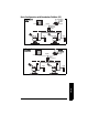
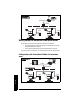
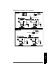
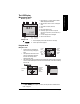
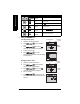
Table Of Contents
- Safety Notes
- FCC Conformity
- CE Electromagnetic Compatibility (EMC) Conformity
- Industry Canada
- The Manual
- Technical Support
- SITRANS LR560 Overview
- Specifications
- Installation
- Wiring
- Local Operation
- Operating via AMS Device Manager
- Functions in AMS Device Manager
- Programming via AMS Device Manager
- Adding a new device
- Startup
- Configuring a new device
- Changing Block Modes
- Configure/Setup Parameters
- Transducer Block Parameters
- Level Transducer Block Parameters
- Operation (LTB)
- Simulation (Input)
- Setup (LTB)
- General
- Calibration
- Rate
- Signal Processing (LTB)
- Range
- Echo Select
- Sampling
- Echo Quality
- Filtering
- TVT Setup
- TVT Shaper 1
- TVT Shaper 2
- TVT Shaper 3
- Echo Profile Parameters (view only)
- Maintenance & Diagnostics (LTB)
- Sensor Lifetime
- Service Schedule
- Communication (LTB)
- Communication:
- Configure/Setup (Liquid Crystal Display Block-LCD)
- Configure/Setup (Diagnostic Transducer Block-DIAG)
- Configure/Setup (Resource Block - RESOURCE)
- Device Diagnostics (Level Transducer Block - LTB)
- Device Diagnostics (Level Control Device Block - LCD)
- Device Diagnostics (Diagnostic Transducer Block - DIAG)
- Device Diagnostics (Resource Block - RESOURCE)
- Password Protection
- AMS Menu Structure
- Parameter Reference
- 1. Quick Start
- 2. Setup
- 2.1. Identification
- 2.2. Device
- 2.3. Sensor
- 2.4. Signal Processing
- 2.4.1. Near Range
- 2.4.2. Far Range
- 2.4.3. Minimum Sensor Value
- 2.4.4. Maximum Sensor Value
- 2.4.5. Echo Select
- 2.4.6. Sampling
- 2.4.7. Echo Quality
- 2.4.8. TVT (Auto False Echo Suppression) Setup
- 2.4.9. TVT Shaper
- 2.4.9.1. Shaper 1-9
- 2.4.9.2. Shaper 10-18
- 2.4.9.3. Shaper 19-27
- 2.4.9.4. Shaper 28-36
- 2.4.9.5. Shaper 37-45
- 2.4.9.6. Shaper 46-54
- 2.4.9.7. Shaper 55-63
- 2.4.9.8. Shaper 64-72
- 2.4.9.9. Shaper 73-81
- 2.4.9.10. Shaper 82-90
- 2.4.9.11. Shaper 91-99
- 2.4.9.12. Shaper 100-108
- 2.4.9.13. Shaper 109-117
- 2.4.9.14. Shaper 118-120
- 2.5. AIFB 1
- 2.6. AIFB 2
- 2.7. Measured Values
- 2.8. Filtering
- 3. Diagnostics
- 4. Service
- 5. Communication
- 6. Security
- 7. Language
- Appendix A: Alphabetical Parameter List
- Appendix B: Troubleshooting
- Appendix C: Maintenance
- Appendix D: Technical Reference
- Principles of Operation
- Echo Processing
- Measurement Range
- Measurement Response
- Damping
- Loss of Echo (LOE)
- Temperature derating curves
- Appendix E: Communications
- Appendix F: Firmware Revision History
- Glossary
- Index
- LCD menu structure

Page 30 SITRANS LR560 (FF) – OPERATING INSTRUCTIONS 7ML19985LY01
mmmmm
Quick Start: local
Local Operation
SITRANS LR560 carries out its level measurement tasks according to settings made via
parameters. The settings can be modified locally using the Local Display Interface (LDI)
which consists of an LCD display with push buttons, or using the LDI in combination with
an infrared handheld programmer.
A Quick Start Wizard provides an easy step-by-step procedure to help you configure the
device for a simple application. There are two ways to access the wizard:
• locally (see
Quick Start Wizard via the LDI push buttons
on page 36 or
Quick Start
Wizard via the handheld programmer
on page 36)
• from a remote location (See
Quick Start Wizard via AMS Device Manager
on
page 46)
See
Level application example
on page 40 for an illustration, and for the complete range
of parameters, see
Parameter Reference
on page 86.
Activating SITRANS LR560
Power up the device. At initial startup, SITRANS LR560 will not begin measurements and
all blocks will be Out of Service until the instrument has been configured
1)
. Completing
the Quick Start Wizard or writing any configuration parameter via the local user interface
causes the device to begin measuring. The Resource Block (RES) and Level Transducer
Block (LTB) will move to Automatic mode
2)
.
A transition screen showing first the Siemens logo and then the current firmware revision
is displayed while the first measurement is being processed.
The first time the device is configured you will be prompted to select a language (English,
German, French, Spanish or Chinese). To change the language again, see Language (7.)
on page 122.
Notes:
• To enter Program mode using the push buttons, press . Press to return to
Measurement mode.
• To toggle between Measurement and Program Mode using the handheld
programmer, press Mode .
1)
See
To configure a device via the local user interface
on page 35. (To configure using
a network configuration tool see
Quick Start Wizard via AMS Device Manager
on
page 46.)
2)
AIFB 1 and AIFB 2 will remain Out of Service (as displayed on the LCD). These blocks
can only be configured and scheduled using a network configuration tool. For more
details, see System Integration in manual
Foundation Fieldbus for Level Instruments
(7ML19985MP01).
push buttons