
User's Manual
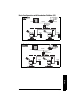
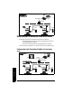
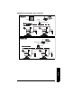
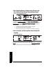
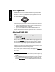
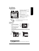
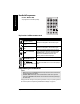
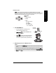
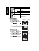
Table Of Contents
- Safety Notes
- FCC Conformity
- CE Electromagnetic Compatibility (EMC) Conformity
- Industry Canada
- The Manual
- Technical Support
- SITRANS LR560 Overview
- Specifications
- Installation
- Wiring
- Local Operation
- Operating via AMS Device Manager
- Functions in AMS Device Manager
- Programming via AMS Device Manager
- Adding a new device
- Startup
- Configuring a new device
- Changing Block Modes
- Configure/Setup Parameters
- Transducer Block Parameters
- Level Transducer Block Parameters
- Operation (LTB)
- Simulation (Input)
- Setup (LTB)
- General
- Calibration
- Rate
- Signal Processing (LTB)
- Range
- Echo Select
- Sampling
- Echo Quality
- Filtering
- TVT Setup
- TVT Shaper 1
- TVT Shaper 2
- TVT Shaper 3
- Echo Profile Parameters (view only)
- Maintenance & Diagnostics (LTB)
- Sensor Lifetime
- Service Schedule
- Communication (LTB)
- Communication:
- Configure/Setup (Liquid Crystal Display Block-LCD)
- Configure/Setup (Diagnostic Transducer Block-DIAG)
- Configure/Setup (Resource Block - RESOURCE)
- Device Diagnostics (Level Transducer Block - LTB)
- Device Diagnostics (Level Control Device Block - LCD)
- Device Diagnostics (Diagnostic Transducer Block - DIAG)
- Device Diagnostics (Resource Block - RESOURCE)
- Password Protection
- AMS Menu Structure
- Parameter Reference
- 1. Quick Start
- 2. Setup
- 2.1. Identification
- 2.2. Device
- 2.3. Sensor
- 2.4. Signal Processing
- 2.4.1. Near Range
- 2.4.2. Far Range
- 2.4.3. Minimum Sensor Value
- 2.4.4. Maximum Sensor Value
- 2.4.5. Echo Select
- 2.4.6. Sampling
- 2.4.7. Echo Quality
- 2.4.8. TVT (Auto False Echo Suppression) Setup
- 2.4.9. TVT Shaper
- 2.4.9.1. Shaper 1-9
- 2.4.9.2. Shaper 10-18
- 2.4.9.3. Shaper 19-27
- 2.4.9.4. Shaper 28-36
- 2.4.9.5. Shaper 37-45
- 2.4.9.6. Shaper 46-54
- 2.4.9.7. Shaper 55-63
- 2.4.9.8. Shaper 64-72
- 2.4.9.9. Shaper 73-81
- 2.4.9.10. Shaper 82-90
- 2.4.9.11. Shaper 91-99
- 2.4.9.12. Shaper 100-108
- 2.4.9.13. Shaper 109-117
- 2.4.9.14. Shaper 118-120
- 2.5. AIFB 1
- 2.6. AIFB 2
- 2.7. Measured Values
- 2.8. Filtering
- 3. Diagnostics
- 4. Service
- 5. Communication
- 6. Security
- 7. Language
- Appendix A: Alphabetical Parameter List
- Appendix B: Troubleshooting
- Appendix C: Maintenance
- Appendix D: Technical Reference
- Principles of Operation
- Echo Processing
- Measurement Range
- Measurement Response
- Damping
- Loss of Echo (LOE)
- Temperature derating curves
- Appendix E: Communications
- Appendix F: Firmware Revision History
- Glossary
- Index
- LCD menu structure

7ML19985LY01 SITRANS LR560 (FF) – INSTRUCTION MANUAL Page 29
Wiring
Instructions specific to hazardous area installations
(Reference European ATEX Directive 94/9/EC, Annex II, 1.0.6)
The following instructions apply to equipment covered by certificate numbers Sira
09ATEX9356X and Sira 09ATEX4357X:
1) For use and assembly and details of marking/coding, refer to the main instructions.
2) The equipment is certified for use as Category 1D, 1/2D and 2D equipment per
certificate Sira 09ATEX9356X and may be used in hazardous zones 20, 21 and 22. The
equipment is also certified for use as Category 3G equipment per certificate Sira
09ATEX4357X and may be used in hazardous zone 2.
3) This equipment has a maximum surface temperature of 139 °C (in an 80 °C ambient).
Refer to the applicable code of practice for selection of this equipment with respect
to specific dust ignition temperatures.
4) The equipment is certified for use in an ambient temperature range of –40 °C to
80 °C.
5) The equipment has not been assessed as a safety related device (as referred to by
Directive 94/9/EC Annex II, clause 1.5).
6) Installation and inspection of this equipment shall be carried out by suitably trained
and authorized personnel in accordance with the applicable code of practice.
7) The equipment shall be installed such that the supply cable is protected from
mechanical damage. The cable shall not be subjected to tension or torque. The
equipment manufacturer is not responsible for providing the supply cable.
8) Repair of this equipment shall be carried out by suitably trained and authorized
personnel in accordance with the applicable code of practice.
Special Conditions for Safe Use
The ‘X’ suffix to the certificate number relates to the following special condition(s) for
safe use:
• Parts of the enclosure may be non-conducting and may generate an ignition-
capable level of electrostatic charge under certain extreme conditions. The user
should ensure that the equipment is not installed in a location where it may be
subjected to external conditions (such as high-pressure steam), which might cause
a build-up of electrostatic charge on non-conducting surfaces.
• The end user must ensure that an ingress protection of at least IP65 is maintained
at each entry to the enclosure by use of a blanking element or cable entry device
that meets the requirements of the protection concepts type ‘n’ or increased safety
‘e’ or flameproof ‘d’.
• The supply to the equipment shall be rated for a prospective short-circuit current of
not more than 10 kA and shall be protected by a suitably-rated fuse
Note: Installation shall be performed only by qualified personnel and in accordance
with local governing regulations.