
User's Manual
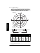
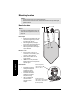
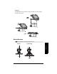
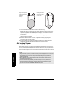
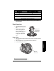
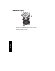
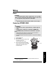
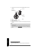
Table Of Contents
- Safety Notes
- FCC Conformity
- CE Electromagnetic Compatibility (EMC) Conformity
- Industry Canada
- The Manual
- Technical Support
- SITRANS LR560 Overview
- Specifications
- Installation
- Wiring
- Local Operation
- Operating via AMS Device Manager
- Functions in AMS Device Manager
- Programming via AMS Device Manager
- Adding a new device
- Startup
- Configuring a new device
- Changing Block Modes
- Configure/Setup Parameters
- Transducer Block Parameters
- Level Transducer Block Parameters
- Operation (LTB)
- Simulation (Input)
- Setup (LTB)
- General
- Calibration
- Rate
- Signal Processing (LTB)
- Range
- Echo Select
- Sampling
- Echo Quality
- Filtering
- TVT Setup
- TVT Shaper 1
- TVT Shaper 2
- TVT Shaper 3
- Echo Profile Parameters (view only)
- Maintenance & Diagnostics (LTB)
- Sensor Lifetime
- Service Schedule
- Communication (LTB)
- Communication:
- Configure/Setup (Liquid Crystal Display Block-LCD)
- Configure/Setup (Diagnostic Transducer Block-DIAG)
- Configure/Setup (Resource Block - RESOURCE)
- Device Diagnostics (Level Transducer Block - LTB)
- Device Diagnostics (Level Control Device Block - LCD)
- Device Diagnostics (Diagnostic Transducer Block - DIAG)
- Device Diagnostics (Resource Block - RESOURCE)
- Password Protection
- AMS Menu Structure
- Parameter Reference
- 1. Quick Start
- 2. Setup
- 2.1. Identification
- 2.2. Device
- 2.3. Sensor
- 2.4. Signal Processing
- 2.4.1. Near Range
- 2.4.2. Far Range
- 2.4.3. Minimum Sensor Value
- 2.4.4. Maximum Sensor Value
- 2.4.5. Echo Select
- 2.4.6. Sampling
- 2.4.7. Echo Quality
- 2.4.8. TVT (Auto False Echo Suppression) Setup
- 2.4.9. TVT Shaper
- 2.4.9.1. Shaper 1-9
- 2.4.9.2. Shaper 10-18
- 2.4.9.3. Shaper 19-27
- 2.4.9.4. Shaper 28-36
- 2.4.9.5. Shaper 37-45
- 2.4.9.6. Shaper 46-54
- 2.4.9.7. Shaper 55-63
- 2.4.9.8. Shaper 64-72
- 2.4.9.9. Shaper 73-81
- 2.4.9.10. Shaper 82-90
- 2.4.9.11. Shaper 91-99
- 2.4.9.12. Shaper 100-108
- 2.4.9.13. Shaper 109-117
- 2.4.9.14. Shaper 118-120
- 2.5. AIFB 1
- 2.6. AIFB 2
- 2.7. Measured Values
- 2.8. Filtering
- 3. Diagnostics
- 4. Service
- 5. Communication
- 6. Security
- 7. Language
- Appendix A: Alphabetical Parameter List
- Appendix B: Troubleshooting
- Appendix C: Maintenance
- Appendix D: Technical Reference
- Principles of Operation
- Echo Processing
- Measurement Range
- Measurement Response
- Damping
- Loss of Echo (LOE)
- Temperature derating curves
- Appendix E: Communications
- Appendix F: Firmware Revision History
- Glossary
- Index
- LCD menu structure

Page 20 SITRANS LR560 (FF) – OPERATING INSTRUCTIONS 7ML1998KL01
mmmmm
Installation
1) For 4" and 6" Aimer: loosen the set screws in the locking ring.
Holding the electronics enclosure firmly, loosen the Aimer locking ring using the C
spanner supplied, until the LR560 drops down slightly. The enclosure can then be
turned freely.
2) Direct SITRANS LR560 so the antenna is pointed at an angle perpendicular to the
material surface, if possible.
3) When the desired position is reached, re-tighten the locking ring using the
C spanner, and tighten set screws.
4) For the 3" Aimer flange, tapered split washers with pressure rated versions are
provided to keep nuts and bolts perpendicular to the flange surface.
Air Purging System
For convenient cleaning, a purging inlet is provided above the antenna. The system pro-
vides an 1/8" inlet (female thread) above the antenna where clean, dry air passes to the
face of the antenna lens to clean it. The customer will supply the purging air by a manual
or automatic valve system.
Notes:
• Purge duration, pressure, and interval, will vary with each application. It is the user’s
responsibility to determine the requirements depending on the application and
cleaning required.
• Short duration bursts of high pressure provide more effective cleaning than
continuous low pressure air.
• It is the customer’s responsibility to ensure that any vacuum or pressure in the
measured vessel is maintained, considering the hole that passes through the
process connection and SITRANS LR560 antenna system.
Aiming is not required
for signal optimization
with 78 GHz
frequency.
Aiming will assist in
measuring material
in the cone.
Aimer