
User's Manual
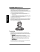
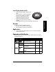
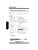
Table Of Contents
- Safety Notes
- FCC Conformity
- CE Electromagnetic Compatibility (EMC) Conformity
- Industry Canada
- The Manual
- Technical Support
- SITRANS LR560 Overview
- Specifications
- Installation
- Wiring
- Local Operation
- Operating via AMS Device Manager
- Functions in AMS Device Manager
- Programming via AMS Device Manager
- Adding a new device
- Startup
- Configuring a new device
- Changing Block Modes
- Configure/Setup Parameters
- Transducer Block Parameters
- Level Transducer Block Parameters
- Operation (LTB)
- Simulation (Input)
- Setup (LTB)
- General
- Calibration
- Rate
- Signal Processing (LTB)
- Range
- Echo Select
- Sampling
- Echo Quality
- Filtering
- TVT Setup
- TVT Shaper 1
- TVT Shaper 2
- TVT Shaper 3
- Echo Profile Parameters (view only)
- Maintenance & Diagnostics (LTB)
- Sensor Lifetime
- Service Schedule
- Communication (LTB)
- Communication:
- Configure/Setup (Liquid Crystal Display Block-LCD)
- Configure/Setup (Diagnostic Transducer Block-DIAG)
- Configure/Setup (Resource Block - RESOURCE)
- Device Diagnostics (Level Transducer Block - LTB)
- Device Diagnostics (Level Control Device Block - LCD)
- Device Diagnostics (Diagnostic Transducer Block - DIAG)
- Device Diagnostics (Resource Block - RESOURCE)
- Password Protection
- AMS Menu Structure
- Parameter Reference
- 1. Quick Start
- 2. Setup
- 2.1. Identification
- 2.2. Device
- 2.3. Sensor
- 2.4. Signal Processing
- 2.4.1. Near Range
- 2.4.2. Far Range
- 2.4.3. Minimum Sensor Value
- 2.4.4. Maximum Sensor Value
- 2.4.5. Echo Select
- 2.4.6. Sampling
- 2.4.7. Echo Quality
- 2.4.8. TVT (Auto False Echo Suppression) Setup
- 2.4.9. TVT Shaper
- 2.4.9.1. Shaper 1-9
- 2.4.9.2. Shaper 10-18
- 2.4.9.3. Shaper 19-27
- 2.4.9.4. Shaper 28-36
- 2.4.9.5. Shaper 37-45
- 2.4.9.6. Shaper 46-54
- 2.4.9.7. Shaper 55-63
- 2.4.9.8. Shaper 64-72
- 2.4.9.9. Shaper 73-81
- 2.4.9.10. Shaper 82-90
- 2.4.9.11. Shaper 91-99
- 2.4.9.12. Shaper 100-108
- 2.4.9.13. Shaper 109-117
- 2.4.9.14. Shaper 118-120
- 2.5. AIFB 1
- 2.6. AIFB 2
- 2.7. Measured Values
- 2.8. Filtering
- 3. Diagnostics
- 4. Service
- 5. Communication
- 6. Security
- 7. Language
- Appendix A: Alphabetical Parameter List
- Appendix B: Troubleshooting
- Appendix C: Maintenance
- Appendix D: Technical Reference
- Principles of Operation
- Echo Processing
- Measurement Range
- Measurement Response
- Damping
- Loss of Echo (LOE)
- Temperature derating curves
- Appendix E: Communications
- Appendix F: Firmware Revision History
- Glossary
- Index
- LCD menu structure

7ML19985LY01 SITRANS LR560 (FF) – OPERATING INSTRUCTIONS Page 9
mmmmm
Specifications
Interface
Communication
• Foundation Fieldbus
• ITK version 5 Blocks supported:
RESOURCE, LTB, AIFB1, AIFB2, PID, LCD, DIAG
Block execution time:
AIFB - 30 ms, PID - 100 ms
Configuration
• remote FF host system or Emerson AMS version 9.0 (PC)
• local Siemens Milltronics infrared handheld programmer
[see
Programmer (infrared keypad)
on page 11],
or Field Communicator 375 [see
Field Communicator
375 (FC375)
on page 147],
or local control buttons
Optional removable
local display interface (LDI)
1)
graphic LCD, with bar graph representing level
Mechanical
Process Connections:
• universal flat-faced flanges
2)
3"/80 mm, 4"/100 mm, 6"/150 mm
- materials stainless steel 316L (1.4404 or 1.4435), or 304
• Aimer flanges
2)
3"/80 mm, 4"/100 mm, 6"/150 mm
- material polyurethane powder-coated cast aluminum
Enclosure
• construction 316L/1.4404 stainless steel
• conduit entry M20x1.5, or ½" NPT
• conduit entry connector M12 connector (shipped with M20 to M12 adaptor)
(optional) or 7/8" connector (shipped with 1/2" NPT to 7/8"
adaptor)
• ingress protection Type 4X/NEMA 4X, Type 6/NEMA 6, IP68
• lid with window polycarbonate (window material)
Lens antenna material
•construction
- 40 m version PEI
- 100 m version PEEK
1)
Display quality will be degraded in temperatures below –20 °C (–4 °F) and above
+65°C (+149 °F).
2)
Universal flange mates with EN 1092-1 (PN16)/ASME B16.5 (150 lb)/JIS 2220 (10K) bolt
hole pattern.