
User's Manual
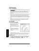
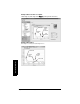
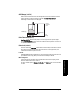
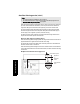
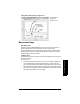
Table Of Contents
- Safety Notes
- FCC Conformity
- CE Electromagnetic Compatibility (EMC) Conformity
- Industry Canada
- The Manual
- Technical Support
- SITRANS LR560 Overview
- Specifications
- Installation
- Wiring
- Local Operation
- Operating via AMS Device Manager
- Functions in AMS Device Manager
- Programming via AMS Device Manager
- Adding a new device
- Startup
- Configuring a new device
- Changing Block Modes
- Configure/Setup Parameters
- Transducer Block Parameters
- Level Transducer Block Parameters
- Operation (LTB)
- Simulation (Input)
- Setup (LTB)
- General
- Calibration
- Rate
- Signal Processing (LTB)
- Range
- Echo Select
- Sampling
- Echo Quality
- Filtering
- TVT Setup
- TVT Shaper 1
- TVT Shaper 2
- TVT Shaper 3
- Echo Profile Parameters (view only)
- Maintenance & Diagnostics (LTB)
- Sensor Lifetime
- Service Schedule
- Communication (LTB)
- Communication:
- Configure/Setup (Liquid Crystal Display Block-LCD)
- Configure/Setup (Diagnostic Transducer Block-DIAG)
- Configure/Setup (Resource Block - RESOURCE)
- Device Diagnostics (Level Transducer Block - LTB)
- Device Diagnostics (Level Control Device Block - LCD)
- Device Diagnostics (Diagnostic Transducer Block - DIAG)
- Device Diagnostics (Resource Block - RESOURCE)
- Password Protection
- AMS Menu Structure
- Parameter Reference
- 1. Quick Start
- 2. Setup
- 2.1. Identification
- 2.2. Device
- 2.3. Sensor
- 2.4. Signal Processing
- 2.4.1. Near Range
- 2.4.2. Far Range
- 2.4.3. Minimum Sensor Value
- 2.4.4. Maximum Sensor Value
- 2.4.5. Echo Select
- 2.4.6. Sampling
- 2.4.7. Echo Quality
- 2.4.8. TVT (Auto False Echo Suppression) Setup
- 2.4.9. TVT Shaper
- 2.4.9.1. Shaper 1-9
- 2.4.9.2. Shaper 10-18
- 2.4.9.3. Shaper 19-27
- 2.4.9.4. Shaper 28-36
- 2.4.9.5. Shaper 37-45
- 2.4.9.6. Shaper 46-54
- 2.4.9.7. Shaper 55-63
- 2.4.9.8. Shaper 64-72
- 2.4.9.9. Shaper 73-81
- 2.4.9.10. Shaper 82-90
- 2.4.9.11. Shaper 91-99
- 2.4.9.12. Shaper 100-108
- 2.4.9.13. Shaper 109-117
- 2.4.9.14. Shaper 118-120
- 2.5. AIFB 1
- 2.6. AIFB 2
- 2.7. Measured Values
- 2.8. Filtering
- 3. Diagnostics
- 4. Service
- 5. Communication
- 6. Security
- 7. Language
- Appendix A: Alphabetical Parameter List
- Appendix B: Troubleshooting
- Appendix C: Maintenance
- Appendix D: Technical Reference
- Principles of Operation
- Echo Processing
- Measurement Range
- Measurement Response
- Damping
- Loss of Echo (LOE)
- Temperature derating curves
- Appendix E: Communications
- Appendix F: Firmware Revision History
- Glossary
- Index
- LCD menu structure

Page 142 SITRANS LR560 (FF)– INSTRUCTION MANUAL 7ML19985LY01
mmmmm
D: Technical Reference
Auto False Echo Suppression (2.4.8.1.)
Auto False Echo Suppression is designed to learn a specific environment (for example, a
particular vessel with known obstructions), and in conjunction with Auto False Echo
Suppression Range to remove false echoes appearing in front of the material echo.
The material level should be below all known obstructions at the moment when Auto
False Echo Suppression learns the echo profile. Ideally the vessel should be empty or
almost empty, and if an agitator is present, it should be running.
The device learns the echo profile over the whole measurement range and the TVT is
shaped around all echoes present at that moment.
Auto False Echo Suppression Range (2.4.8.2.)
Auto False Echo Suppression Range specifies the range within which the learned TVT is
applied. Default TVT is applied over the remainder of the range.
The learned TVT screens out the false echoes caused by obstructions. The default TVT
allows the material echo to rise above it.
Auto False Echo Suppression Range must be set to a distance shorter than the distance
to the material level when the environment was learned, to avoid the material echo being
screened out.
Notes:
• To access this feature via AMS see
TVT
on page 54.
• For detailed instructions on using this feature via the handheld programmer see
Auto False Echo Suppression (2.4.8.1.) on page 100.
High Cal. Pt.
= 1
obstruction
at 1.9 m
material level at
3.9 m
false
echo
material
echo
default
TVT
sensor reference point
Example before Auto False Echo Suppression