
User's Manual
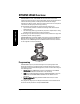
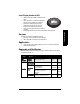
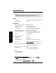
Table Of Contents
- Safety Notes
- FCC Conformity
- CE Electromagnetic Compatibility (EMC) Conformity
- Industry Canada
- The Manual
- Technical Support
- SITRANS LR560 Overview
- Specifications
- Installation
- Wiring
- Local Operation
- Operating via AMS Device Manager
- Functions in AMS Device Manager
- Programming via AMS Device Manager
- Adding a new device
- Startup
- Configuring a new device
- Changing Block Modes
- Configure/Setup Parameters
- Transducer Block Parameters
- Level Transducer Block Parameters
- Operation (LTB)
- Simulation (Input)
- Setup (LTB)
- General
- Calibration
- Rate
- Signal Processing (LTB)
- Range
- Echo Select
- Sampling
- Echo Quality
- Filtering
- TVT Setup
- TVT Shaper 1
- TVT Shaper 2
- TVT Shaper 3
- Echo Profile Parameters (view only)
- Maintenance & Diagnostics (LTB)
- Sensor Lifetime
- Service Schedule
- Communication (LTB)
- Communication:
- Configure/Setup (Liquid Crystal Display Block-LCD)
- Configure/Setup (Diagnostic Transducer Block-DIAG)
- Configure/Setup (Resource Block - RESOURCE)
- Device Diagnostics (Level Transducer Block - LTB)
- Device Diagnostics (Level Control Device Block - LCD)
- Device Diagnostics (Diagnostic Transducer Block - DIAG)
- Device Diagnostics (Resource Block - RESOURCE)
- Password Protection
- AMS Menu Structure
- Parameter Reference
- 1. Quick Start
- 2. Setup
- 2.1. Identification
- 2.2. Device
- 2.3. Sensor
- 2.4. Signal Processing
- 2.4.1. Near Range
- 2.4.2. Far Range
- 2.4.3. Minimum Sensor Value
- 2.4.4. Maximum Sensor Value
- 2.4.5. Echo Select
- 2.4.6. Sampling
- 2.4.7. Echo Quality
- 2.4.8. TVT (Auto False Echo Suppression) Setup
- 2.4.9. TVT Shaper
- 2.4.9.1. Shaper 1-9
- 2.4.9.2. Shaper 10-18
- 2.4.9.3. Shaper 19-27
- 2.4.9.4. Shaper 28-36
- 2.4.9.5. Shaper 37-45
- 2.4.9.6. Shaper 46-54
- 2.4.9.7. Shaper 55-63
- 2.4.9.8. Shaper 64-72
- 2.4.9.9. Shaper 73-81
- 2.4.9.10. Shaper 82-90
- 2.4.9.11. Shaper 91-99
- 2.4.9.12. Shaper 100-108
- 2.4.9.13. Shaper 109-117
- 2.4.9.14. Shaper 118-120
- 2.5. AIFB 1
- 2.6. AIFB 2
- 2.7. Measured Values
- 2.8. Filtering
- 3. Diagnostics
- 4. Service
- 5. Communication
- 6. Security
- 7. Language
- Appendix A: Alphabetical Parameter List
- Appendix B: Troubleshooting
- Appendix C: Maintenance
- Appendix D: Technical Reference
- Principles of Operation
- Echo Processing
- Measurement Range
- Measurement Response
- Damping
- Loss of Echo (LOE)
- Temperature derating curves
- Appendix E: Communications
- Appendix F: Firmware Revision History
- Glossary
- Index
- LCD menu structure

Page 8 SITRANS LR560 (FF) – OPERATING INSTRUCTIONS 7ML19985LY01
mmmmm
Specifications
Specifications
Power
Bus powered 9 to 32 V DC, per IEC 61158-2 (Foundation Fieldbus)
Current consumed 13.5 mA
Performance
Reference operating conditions according to IEC 60770-1
• ambient temperature +15 to +25
o
C (+59 to +77
o
F)
• humidity 45% to 75% relative humidity
• ambient pressure 860 to 1060 mbar g (86,000 to 106,000 N/m
2
g)
Measurement Accuracy
1)
(measured in accordance with IEC 60770-1)
• Maximum measured error Greater of 25 mm (1") or 0.25% of range from
minimum detectable distance to full range
Frequency 78 to 79 GHz FMCW
Max. measurement range
2)
• 40 m version 40 m (131 ft)
• 100 m version 100 m (328 ft)
Min. detectable distance 300 mm (11.8") from sensor reference point
Update time
3)
Maximum 10 seconds, depending on setting for
Response Rate (2.3.6.1.)
Influence of ambient temperature <0.003%/K (average over full temperature range,
referenced to maximum range)
Dielectric constant of material measured
• Minimum dK = 1.6 for ranges to 20 m (65.6 ft) range
= 2.5 for ranges to 100 m (328 ft) range
Memory
• non-volatile EEPROM
• no battery required
Notes:
• Siemens Milltronics makes every attempt to ensure the accuracy of these
specifications but reserves the right to change them at any time.
1)
Reference conditions: Position Detect (2.4.5.2.) set to Center and Algorithm
(2.4.5.1.) set to True First Echo.
2)
From sensor reference point.
3)
Reference conditions: Response Rate (2.3.6.1.) set to FAST.