
User's Manual

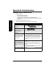
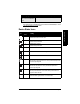
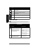
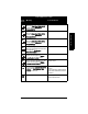
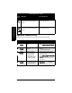
Table Of Contents
- Safety Notes
- FCC Conformity
- CE Electromagnetic Compatibility (EMC) Conformity
- Industry Canada
- The Manual
- Technical Support
- SITRANS LR560 Overview
- Specifications
- Installation
- Wiring
- Local Operation
- Operating via AMS Device Manager
- Functions in AMS Device Manager
- Programming via AMS Device Manager
- Adding a new device
- Startup
- Configuring a new device
- Changing Block Modes
- Configure/Setup Parameters
- Transducer Block Parameters
- Level Transducer Block Parameters
- Operation (LTB)
- Simulation (Input)
- Setup (LTB)
- General
- Calibration
- Rate
- Signal Processing (LTB)
- Range
- Echo Select
- Sampling
- Echo Quality
- Filtering
- TVT Setup
- TVT Shaper 1
- TVT Shaper 2
- TVT Shaper 3
- Echo Profile Parameters (view only)
- Maintenance & Diagnostics (LTB)
- Sensor Lifetime
- Service Schedule
- Communication (LTB)
- Communication:
- Configure/Setup (Liquid Crystal Display Block-LCD)
- Configure/Setup (Diagnostic Transducer Block-DIAG)
- Configure/Setup (Resource Block - RESOURCE)
- Device Diagnostics (Level Transducer Block - LTB)
- Device Diagnostics (Level Control Device Block - LCD)
- Device Diagnostics (Diagnostic Transducer Block - DIAG)
- Device Diagnostics (Resource Block - RESOURCE)
- Password Protection
- AMS Menu Structure
- Parameter Reference
- 1. Quick Start
- 2. Setup
- 2.1. Identification
- 2.2. Device
- 2.3. Sensor
- 2.4. Signal Processing
- 2.4.1. Near Range
- 2.4.2. Far Range
- 2.4.3. Minimum Sensor Value
- 2.4.4. Maximum Sensor Value
- 2.4.5. Echo Select
- 2.4.6. Sampling
- 2.4.7. Echo Quality
- 2.4.8. TVT (Auto False Echo Suppression) Setup
- 2.4.9. TVT Shaper
- 2.4.9.1. Shaper 1-9
- 2.4.9.2. Shaper 10-18
- 2.4.9.3. Shaper 19-27
- 2.4.9.4. Shaper 28-36
- 2.4.9.5. Shaper 37-45
- 2.4.9.6. Shaper 46-54
- 2.4.9.7. Shaper 55-63
- 2.4.9.8. Shaper 64-72
- 2.4.9.9. Shaper 73-81
- 2.4.9.10. Shaper 82-90
- 2.4.9.11. Shaper 91-99
- 2.4.9.12. Shaper 100-108
- 2.4.9.13. Shaper 109-117
- 2.4.9.14. Shaper 118-120
- 2.5. AIFB 1
- 2.6. AIFB 2
- 2.7. Measured Values
- 2.8. Filtering
- 3. Diagnostics
- 4. Service
- 5. Communication
- 6. Security
- 7. Language
- Appendix A: Alphabetical Parameter List
- Appendix B: Troubleshooting
- Appendix C: Maintenance
- Appendix D: Technical Reference
- Principles of Operation
- Echo Processing
- Measurement Range
- Measurement Response
- Damping
- Loss of Echo (LOE)
- Temperature derating curves
- Appendix E: Communications
- Appendix F: Firmware Revision History
- Glossary
- Index
- LCD menu structure

Page 128 SITRANS LR560 (FF)– INSTRUCTION MANUAL 7ML19985LY01
mmmmm
B: Troubleshooting
Appendix B: Troubleshooting
Communication Troubleshooting
1. Check the following:
• There is power at the instrument.
• The LCD shows the relevant data.
• The device can be programmed using the handheld programmer.
• If any fault codes are being displayed see
General Fault Codes
on page 130 for a
detailed list.
2. Verify that the wiring connections are correct.
3. See the table below for specific symptoms (continued on next page).
Symptom Corrective action
The device cannot be pro-
grammed via the handheld
programmer.
Make sure Write Protection (6.2.1.) is set to the unlock
value, and that Local Operation (6.2.2.) is enabled.
You try to set a SITRANS
LR560 parameter via remote
communications but the
parameter remains
unchanged.
• Ensure Remote Lockout (6.1.1.) on page 121 is disabled.
•Ensure Write Protection (6.2.1.) on page 122 is set to
the unlock value.
The controller value equals
the display value but does
not correspond to actual
material level.
•
Ensure Scaling in AIFB 1 is correctly entered.
• Ensure High Calibration Point is correctly entered.
• View the echo profile to see if the wrong echo is
being selected. If so, see
Operation Troubleshooting
on page 134 for possible causes and corrective
action.
The controller value is not
equal to the displayed value
(regardless of actual material
level).
• Confirm you are looking at the right spot in the con-
troller.
• Ensure scaling has not been programmed into the
controller: all scaling should be performed by the
LR560.
• Check the network to ensure the controller is com-
municating with the LR560.
Only the AIFB 1 and AIFB 2
parameters are displayed via
LUI
•Ensure Local Operation (6.2.2.) on page 122 is enabled