
User's Manual
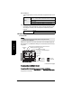
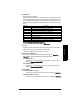
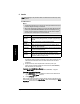
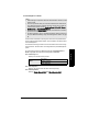
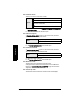
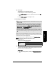
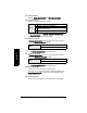
Table Of Contents
- Safety Notes
- FCC Conformity
- CE Electromagnetic Compatibility (EMC) Conformity
- Industry Canada
- The Manual
- Technical Support
- SITRANS LR560 Overview
- Specifications
- Installation
- Wiring
- Local Operation
- Operating via AMS Device Manager
- Functions in AMS Device Manager
- Programming via AMS Device Manager
- Adding a new device
- Startup
- Configuring a new device
- Changing Block Modes
- Configure/Setup Parameters
- Transducer Block Parameters
- Level Transducer Block Parameters
- Operation (LTB)
- Simulation (Input)
- Setup (LTB)
- General
- Calibration
- Rate
- Signal Processing (LTB)
- Range
- Echo Select
- Sampling
- Echo Quality
- Filtering
- TVT Setup
- TVT Shaper 1
- TVT Shaper 2
- TVT Shaper 3
- Echo Profile Parameters (view only)
- Maintenance & Diagnostics (LTB)
- Sensor Lifetime
- Service Schedule
- Communication (LTB)
- Communication:
- Configure/Setup (Liquid Crystal Display Block-LCD)
- Configure/Setup (Diagnostic Transducer Block-DIAG)
- Configure/Setup (Resource Block - RESOURCE)
- Device Diagnostics (Level Transducer Block - LTB)
- Device Diagnostics (Level Control Device Block - LCD)
- Device Diagnostics (Diagnostic Transducer Block - DIAG)
- Device Diagnostics (Resource Block - RESOURCE)
- Password Protection
- AMS Menu Structure
- Parameter Reference
- 1. Quick Start
- 2. Setup
- 2.1. Identification
- 2.2. Device
- 2.3. Sensor
- 2.4. Signal Processing
- 2.4.1. Near Range
- 2.4.2. Far Range
- 2.4.3. Minimum Sensor Value
- 2.4.4. Maximum Sensor Value
- 2.4.5. Echo Select
- 2.4.6. Sampling
- 2.4.7. Echo Quality
- 2.4.8. TVT (Auto False Echo Suppression) Setup
- 2.4.9. TVT Shaper
- 2.4.9.1. Shaper 1-9
- 2.4.9.2. Shaper 10-18
- 2.4.9.3. Shaper 19-27
- 2.4.9.4. Shaper 28-36
- 2.4.9.5. Shaper 37-45
- 2.4.9.6. Shaper 46-54
- 2.4.9.7. Shaper 55-63
- 2.4.9.8. Shaper 64-72
- 2.4.9.9. Shaper 73-81
- 2.4.9.10. Shaper 82-90
- 2.4.9.11. Shaper 91-99
- 2.4.9.12. Shaper 100-108
- 2.4.9.13. Shaper 109-117
- 2.4.9.14. Shaper 118-120
- 2.5. AIFB 1
- 2.6. AIFB 2
- 2.7. Measured Values
- 2.8. Filtering
- 3. Diagnostics
- 4. Service
- 5. Communication
- 6. Security
- 7. Language
- Appendix A: Alphabetical Parameter List
- Appendix B: Troubleshooting
- Appendix C: Maintenance
- Appendix D: Technical Reference
- Principles of Operation
- Echo Processing
- Measurement Range
- Measurement Response
- Damping
- Loss of Echo (LOE)
- Temperature derating curves
- Appendix E: Communications
- Appendix F: Firmware Revision History
- Glossary
- Index
- LCD menu structure

Page 108 SITRANS LR560 (FF) – INSTRUCTION MANUAL 7ML19985LY01
mmmmm
Parameters
2.8.2. Reform Echo
Smooths jagged peaks in the echo profile. Reforms fragmented echoes into one
echo.
2.8.3. Average amount
The fraction of the old shot data that is kept for averaging purposes. A higher
value will give a smoother profile at the expense of a slower echo profile
response.
3. Diagnostics
3.1. Echo Profile
Allows you to request the current echo profile either via the handheld programmer,
the local buttons, or via AMS Device Manager. For more detail see Echo Processing
on page 138.
(continued on next page)
To request a profile via AMS Device Manager:
• see
Echo Profile
on page 56.
To request a profile via the handheld programmer or local control buttons:
In PROGRAM mode, navigate to Echo Profile (3.1.). (See
Requesting an Echo Profile
on page 39 for more details.)
Values
Range: 0 to 255 samples.
Default:
0 (reset to 10 after a Quick Start has been completed)
0 = OFF
greater = wider
Recommended: 5 to 20 samples. Wider is not recommended.
Values
0.0 to 1.0
Default: 0.75
Notes:
• LTB Block must be put back to AUTO mode to display Echo Profile.
• Selected icon is highlighted.
exit icon,
selected
exit icon,
deselected
exit
pan up/down
distance from flange face to target
Algorithm selection (trueFirst echo)
TVT
curve
material
level
confidence
value
distance from Low Calibration Point to vertical cross-hair
measure
zoom in/out
pan left/right - selected/highlighted
Measurement Range (0 to 50 m for example purposes)
Echo Amplitude (dB)