
User's Manual
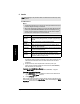
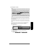
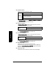
Table Of Contents
- Safety Notes
- FCC Conformity
- CE Electromagnetic Compatibility (EMC) Conformity
- Industry Canada
- The Manual
- Technical Support
- SITRANS LR560 Overview
- Specifications
- Installation
- Wiring
- Local Operation
- Operating via AMS Device Manager
- Functions in AMS Device Manager
- Programming via AMS Device Manager
- Adding a new device
- Startup
- Configuring a new device
- Changing Block Modes
- Configure/Setup Parameters
- Transducer Block Parameters
- Level Transducer Block Parameters
- Operation (LTB)
- Simulation (Input)
- Setup (LTB)
- General
- Calibration
- Rate
- Signal Processing (LTB)
- Range
- Echo Select
- Sampling
- Echo Quality
- Filtering
- TVT Setup
- TVT Shaper 1
- TVT Shaper 2
- TVT Shaper 3
- Echo Profile Parameters (view only)
- Maintenance & Diagnostics (LTB)
- Sensor Lifetime
- Service Schedule
- Communication (LTB)
- Communication:
- Configure/Setup (Liquid Crystal Display Block-LCD)
- Configure/Setup (Diagnostic Transducer Block-DIAG)
- Configure/Setup (Resource Block - RESOURCE)
- Device Diagnostics (Level Transducer Block - LTB)
- Device Diagnostics (Level Control Device Block - LCD)
- Device Diagnostics (Diagnostic Transducer Block - DIAG)
- Device Diagnostics (Resource Block - RESOURCE)
- Password Protection
- AMS Menu Structure
- Parameter Reference
- 1. Quick Start
- 2. Setup
- 2.1. Identification
- 2.2. Device
- 2.3. Sensor
- 2.4. Signal Processing
- 2.4.1. Near Range
- 2.4.2. Far Range
- 2.4.3. Minimum Sensor Value
- 2.4.4. Maximum Sensor Value
- 2.4.5. Echo Select
- 2.4.6. Sampling
- 2.4.7. Echo Quality
- 2.4.8. TVT (Auto False Echo Suppression) Setup
- 2.4.9. TVT Shaper
- 2.4.9.1. Shaper 1-9
- 2.4.9.2. Shaper 10-18
- 2.4.9.3. Shaper 19-27
- 2.4.9.4. Shaper 28-36
- 2.4.9.5. Shaper 37-45
- 2.4.9.6. Shaper 46-54
- 2.4.9.7. Shaper 55-63
- 2.4.9.8. Shaper 64-72
- 2.4.9.9. Shaper 73-81
- 2.4.9.10. Shaper 82-90
- 2.4.9.11. Shaper 91-99
- 2.4.9.12. Shaper 100-108
- 2.4.9.13. Shaper 109-117
- 2.4.9.14. Shaper 118-120
- 2.5. AIFB 1
- 2.6. AIFB 2
- 2.7. Measured Values
- 2.8. Filtering
- 3. Diagnostics
- 4. Service
- 5. Communication
- 6. Security
- 7. Language
- Appendix A: Alphabetical Parameter List
- Appendix B: Troubleshooting
- Appendix C: Maintenance
- Appendix D: Technical Reference
- Principles of Operation
- Echo Processing
- Measurement Range
- Measurement Response
- Damping
- Loss of Echo (LOE)
- Temperature derating curves
- Appendix E: Communications
- Appendix F: Firmware Revision History
- Glossary
- Index
- LCD menu structure

7ML19985LY01 SITRANS LR560 (FF) – INSTRUCTION MANUAL Page 107
mmmmm
Parameters
2.5.7. Display
2.5.7.1. Filter Time Constant
The time constant for the damping filter. The damping filter smooths out the
response to a sudden change in level. This is a first order filter and the
engineering unit is always in seconds. See Damping on page 144 for more
detail.)
2.6. AIFB 2
See AIFB 1 (2.5.): the parameters for AIFB 2 are identical to AIFB 1.
2.7. Measured Values
(for diagnostic purposes)
Read only. Allows you to view measured values for diagnostic purposes.
2.7.1. Main Output (PV– Primary Value)
The value for Level.
In AMS Device Manager, see
Process Variables (Level Transducer Block - LTB)
on page 73.
2.7.2. Output, no linearization (SV1 – Secondary Value 1)
The value for Level.
2.7.3. Output, no level offsets (SV2 – Secondary Value 2)
The value for Distance.
2.8. Filtering
2.8.1. Narrow Echo Filter
Filters out echoes of a specific width.
To remove a false echo from the Echo Profile, take its width in mm and multiply
it by 0.013. Enter the result.
For example, to filter out a spike with 500 mm width, enter 6 or 7 (the closest
integer product of 500 x 0.013).
When a value is keyed in, the nearest acceptable value is entered.
Values
Range: Any non-negative number can be entered
Unit: s
Default: 0
a)
a)
To meet accuracy specification, Filter Time Constant (PV_FTIME)
must be changed from default of 0.0 s to a minimum of 10.0 seconds.
(See
Performance
on page 8.)
Values
Range: 0 to 255. Default: 0
0 = OFF
greater = wider