
User's Manual
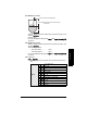
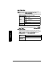
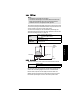
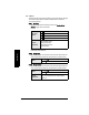

Table Of Contents
- Safety Notes
- FCC Conformity
- CE Electromagnetic Compatibility (EMC) Conformity
- Industry Canada
- The Manual
- Technical Support
- SITRANS LR560 Overview
- Specifications
- Installation
- Wiring
- Local Operation
- Operating via AMS Device Manager
- Functions in AMS Device Manager
- Programming via AMS Device Manager
- Adding a new device
- Startup
- Configuring a new device
- Changing Block Modes
- Configure/Setup Parameters
- Transducer Block Parameters
- Level Transducer Block Parameters
- Operation (LTB)
- Simulation (Input)
- Setup (LTB)
- General
- Calibration
- Rate
- Signal Processing (LTB)
- Range
- Echo Select
- Sampling
- Echo Quality
- Filtering
- TVT Setup
- TVT Shaper 1
- TVT Shaper 2
- TVT Shaper 3
- Echo Profile Parameters (view only)
- Maintenance & Diagnostics (LTB)
- Sensor Lifetime
- Service Schedule
- Communication (LTB)
- Communication:
- Configure/Setup (Liquid Crystal Display Block-LCD)
- Configure/Setup (Diagnostic Transducer Block-DIAG)
- Configure/Setup (Resource Block - RESOURCE)
- Device Diagnostics (Level Transducer Block - LTB)
- Device Diagnostics (Level Control Device Block - LCD)
- Device Diagnostics (Diagnostic Transducer Block - DIAG)
- Device Diagnostics (Resource Block - RESOURCE)
- Password Protection
- AMS Menu Structure
- Parameter Reference
- 1. Quick Start
- 2. Setup
- 2.1. Identification
- 2.2. Device
- 2.3. Sensor
- 2.4. Signal Processing
- 2.4.1. Near Range
- 2.4.2. Far Range
- 2.4.3. Minimum Sensor Value
- 2.4.4. Maximum Sensor Value
- 2.4.5. Echo Select
- 2.4.6. Sampling
- 2.4.7. Echo Quality
- 2.4.8. TVT (Auto False Echo Suppression) Setup
- 2.4.9. TVT Shaper
- 2.4.9.1. Shaper 1-9
- 2.4.9.2. Shaper 10-18
- 2.4.9.3. Shaper 19-27
- 2.4.9.4. Shaper 28-36
- 2.4.9.5. Shaper 37-45
- 2.4.9.6. Shaper 46-54
- 2.4.9.7. Shaper 55-63
- 2.4.9.8. Shaper 64-72
- 2.4.9.9. Shaper 73-81
- 2.4.9.10. Shaper 82-90
- 2.4.9.11. Shaper 91-99
- 2.4.9.12. Shaper 100-108
- 2.4.9.13. Shaper 109-117
- 2.4.9.14. Shaper 118-120
- 2.5. AIFB 1
- 2.6. AIFB 2
- 2.7. Measured Values
- 2.8. Filtering
- 3. Diagnostics
- 4. Service
- 5. Communication
- 6. Security
- 7. Language
- Appendix A: Alphabetical Parameter List
- Appendix B: Troubleshooting
- Appendix C: Maintenance
- Appendix D: Technical Reference
- Principles of Operation
- Echo Processing
- Measurement Range
- Measurement Response
- Damping
- Loss of Echo (LOE)
- Temperature derating curves
- Appendix E: Communications
- Appendix F: Firmware Revision History
- Glossary
- Index
- LCD menu structure

7ML19985LY01 SITRANS LR560 (FF) – INSTRUCTION MANUAL Page 103
mmmmm
Parameters
2.5. AIFB 1
2.5.1. Static Revision Number
The revision level of the static data associated with Analog Input Function
Block 1. The Static Revision No. is updated whenever a configuration
parameter is changed.
2.5.2. Mode
Used to request an operating mode from the Analog Input Function Block. It
allows you to put SITRANS LR560 into Manual mode (used in conjunction with
Simulation) or Out-of-Service mode for maintenance purposes.
Manual Mode can be used when simulating output.
Notes:
• All AIFB parameters are
read only
via local operation, and not visible to AMS
Device Manager. They can be changed only by a remote host such as DeltaV or
NI-FBUS-Configurator.
• AIFB 1 and AIFB 2 are not active upon initial startup. These blocks will show Out
of Service on the LCD at startup. If these blocks are needed for an FF
application, use a tool such as DeltaV or NI-FBUS-Configurator to configure and
schedule the blocks. See the manual
Foundation Fieldbus for Level instruments
(7ML19985MP01)
for details.
• Default settings in the parameter tables are indicated with an asterisk (*) unless
explicitly stated.
Note: Ensure that Mode is returned to AUTO when simulation or
maintenance are completed.
Setting Description Output value
AUTO automatic the automatically-recorded measured value
MAN manual a manually-set fixed simulation value
O/S function block
disabled
the preset safety value