
User's Manual
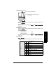
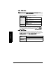
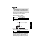
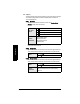
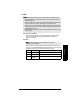
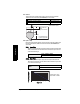
Table Of Contents
- Safety Notes
- FCC Conformity
- CE Electromagnetic Compatibility (EMC) Conformity
- Industry Canada
- The Manual
- Technical Support
- SITRANS LR560 Overview
- Specifications
- Installation
- Wiring
- Local Operation
- Operating via AMS Device Manager
- Functions in AMS Device Manager
- Programming via AMS Device Manager
- Adding a new device
- Startup
- Configuring a new device
- Changing Block Modes
- Configure/Setup Parameters
- Transducer Block Parameters
- Level Transducer Block Parameters
- Operation (LTB)
- Simulation (Input)
- Setup (LTB)
- General
- Calibration
- Rate
- Signal Processing (LTB)
- Range
- Echo Select
- Sampling
- Echo Quality
- Filtering
- TVT Setup
- TVT Shaper 1
- TVT Shaper 2
- TVT Shaper 3
- Echo Profile Parameters (view only)
- Maintenance & Diagnostics (LTB)
- Sensor Lifetime
- Service Schedule
- Communication (LTB)
- Communication:
- Configure/Setup (Liquid Crystal Display Block-LCD)
- Configure/Setup (Diagnostic Transducer Block-DIAG)
- Configure/Setup (Resource Block - RESOURCE)
- Device Diagnostics (Level Transducer Block - LTB)
- Device Diagnostics (Level Control Device Block - LCD)
- Device Diagnostics (Diagnostic Transducer Block - DIAG)
- Device Diagnostics (Resource Block - RESOURCE)
- Password Protection
- AMS Menu Structure
- Parameter Reference
- 1. Quick Start
- 2. Setup
- 2.1. Identification
- 2.2. Device
- 2.3. Sensor
- 2.4. Signal Processing
- 2.4.1. Near Range
- 2.4.2. Far Range
- 2.4.3. Minimum Sensor Value
- 2.4.4. Maximum Sensor Value
- 2.4.5. Echo Select
- 2.4.6. Sampling
- 2.4.7. Echo Quality
- 2.4.8. TVT (Auto False Echo Suppression) Setup
- 2.4.9. TVT Shaper
- 2.4.9.1. Shaper 1-9
- 2.4.9.2. Shaper 10-18
- 2.4.9.3. Shaper 19-27
- 2.4.9.4. Shaper 28-36
- 2.4.9.5. Shaper 37-45
- 2.4.9.6. Shaper 46-54
- 2.4.9.7. Shaper 55-63
- 2.4.9.8. Shaper 64-72
- 2.4.9.9. Shaper 73-81
- 2.4.9.10. Shaper 82-90
- 2.4.9.11. Shaper 91-99
- 2.4.9.12. Shaper 100-108
- 2.4.9.13. Shaper 109-117
- 2.4.9.14. Shaper 118-120
- 2.5. AIFB 1
- 2.6. AIFB 2
- 2.7. Measured Values
- 2.8. Filtering
- 3. Diagnostics
- 4. Service
- 5. Communication
- 6. Security
- 7. Language
- Appendix A: Alphabetical Parameter List
- Appendix B: Troubleshooting
- Appendix C: Maintenance
- Appendix D: Technical Reference
- Principles of Operation
- Echo Processing
- Measurement Range
- Measurement Response
- Damping
- Loss of Echo (LOE)
- Temperature derating curves
- Appendix E: Communications
- Appendix F: Firmware Revision History
- Glossary
- Index
- LCD menu structure

Page 98 SITRANS LR560 (FF) – INSTRUCTION MANUAL 7ML19985LY01
mmmmm
Parameters
2.4.6. Sampling
Provides a method of checking the reliability of a new echo before accepting it
as the valid reading, based on numbers of samples above or below the
currently selected echo.
2.4.6.1. Echo Lock
Selects the measurement verification process. See Position Detect
(2.4.5.2.) on page 139 for more details.
For radar applications, Material Agitator is the most often used setting, to
avoid agitator blade detection.
2.4.6.2. Sampling Up
Specifies the number of consecutive echoes that must appear above the
echo currently selected, before the measurement is accepted as valid.
2.4.6.3. Sampling Down
Specifies the number of consecutive echoes that must appear below the
echo currently selected, before the measurement is accepted as valid.
Echo Lock
Options
0
Lock Off (no verification)
1
Maximum Verification
2
* Material Agitator
3
Total Lock
Related
parameters
Fill Rate/Min (2.3.6.2.)
Empty rate/Min (2.3.6.3.)
Sampling Up (2.4.6.2.)
Sampling Down (2.4.6.3.)
Algorithm (2.4.5.1.)
Values
Range: 1 to 50
Default: 5
Values
Range: 1 to 50
Default: 2
Related
parameters
Echo Lock (2.4.6.1.) If Echo Lock set to any value
other than its default (2), then Down Sampling
default = 5.