Radar Transmitters SITRANS LR560 (mA/HART) Dr Fi af rm t_ w Rev ar . e 1. 1. 000 03 .0 0.
Safety Guidelines: Warning notices must be observed to ensure personal safety as well as that of others, and to protect the product and the connected equipment. These warning notices are accompanied by a clarification of the level of caution to be observed. Qualified Personnel: This device/system may only be set up and operated in conjunction with this manual. Qualified personnel are only authorized to install and operate this equipment in accordance with established safety practices and standards.
Table of Contents Programming ................................................................................................................................5 Local Display Interface (LDI) ....................................................................................................6 Versions ..................................................................................................................................................6 Applications .................................................
Table of Contents mmmmm Requesting an Echo Profile ..............................................................................................................35 Level application example ................................................................................................................36 Operating via SIMATIC PDM .........................................................................................37 Functions in SIMATIC PDM .............................................................
Appendix B: Troubleshooting .....................................................................................114 Communication Troubleshooting ..................................................................................................114 Device Status Icons .........................................................................................................................115 General Fault Codes ..................................................................................................
Table of Contents mmmmm Typical Connection Drawing ................................................................................................132 Allowable operating area of SITRANS LR560 ..................................................................133 Startup Behavior .....................................................................................................................133 Appendix F: HART Communications .........................................................................
Safety Notes Special attention must be paid to warnings and notes highlighted from the rest of the text by grey boxes. WARNING symbol relates to a caution symbol on the product, and means that failure to observe the necessary precautions can result in death, serious injury, and/or considerable material damage.
CE Electromagnetic Compatibility (EMC) Conformity This equipment has been tested and found to comply with the following EMC Standards: EMC Standard CISPR 11:2004/EN 55011:1998+A1:1999&A2:2002, CLASS B EN 61326:1997+A1:1998+A2:2001+A3:2003 (IEC 61326:2002) SITRANS LR560 mmmmm EN61000-4-2:2001 EN61000-4-3:2002 EN61000-4-4:2004 EN61000-4-5:2001 EN61000-4-6:2004 EN61000-4-8:2001 Title Limits and methods of measurements of radio disturbance characteristics of industrial, scientific, and medical (ISM) r
d) This level probing device is only permitted for installation inside enclosed containers. The installer/user of this device shall ensure that it is at least 10 km from the Penticton radio astronomy station (British Columbia latitude: 49° 19' 12" N, longitude: 119° 37'12" W). For devices not meeting this 10 km separation (e.g.
For on-line technical support go to: www.siemens.com/automation/support-request • Enter the device name (SITRANS LR560) or order number, then click on Search, and select the appropriate product type. Click on Next. • You will be prompted to enter a keyword describing your issue. Then either browse the relevant documentation, or click on Next to email a detailed description of your issue to Siemens Technical Support staff.
SITRANS LR560 Overview SITRANS LR560 is a 2-wire, 78 GHz FMCW radar level transmitter for continuous monitoring of solids in vessels to a range of 100 m (329 ft). The plug and play performance is ideal for all solids applications, including those with extreme dust and high temperatures to +200 °C (+392 °F). The device is an electronic circuit coupled to a lens antenna and flange for quick and easy positioning.
Local Display Interface (LDI) • LDI may be ordered installed or added later as an option can be mounted in 1 of 4 positions at 90 degree intervals, for easy viewing after installation displays level and diagnostic information including echo profile and trend over time backlit for easy viewing in dimly lit areas allows you to copy parameters from one device to another provides high speed firmware transfer capabilities for future upgrades • • • • SITRANS LR560 mmmmm • Versions Two different versions of
Specifications Note: Siemens Milltronics makes every attempt to ensure the accuracy of these specifications but reserves the right to change them at any time. Power Nominal 24 V DC with max.
Memory: • non-volatile EEPROM • no battery required Interface Analog output • signal range • fail signal • load Communication: HART • Load multi-wire: ≤ 1500 m (4921 ft) • Protocol HART2), Version 6.0 • local Specifications 230 to 550 Ω, 230 to 500 Ω when connecting a coupling module • Max. Line Length1) Configuration • remote mmmmm 4 to 20 mA (±0.02 mA accuracy) upper limit 20 to 22.6 mA adjustable lower limit 3.56 to 4 mA adjustable 3.56 mA to 22.6 mA; or last value Max.
Enclosure • construction • conduit entry • conduit entry connector optional) • ingress protection • lid with window Lens antenna material • construction 316L/1.4404 stainless steel M20x1.
Approvals Note: The device label lists the approvals that apply to your device. • General CSAUS/C, FM, CE, C-TICK • Radio R&TTE (Europe), FCC, Industry Canada, • Hazardous Non-sparking/ Energy Limited1) (Europe) Dust Ignition Proof 2)(Europe/International) Dust Ignition Proof 3) (US/Canada) Non-incendive2) (US/Canada) ATEX II 3G Ex nA/nL IIC T4 Gc ATEX II 1D, 1/2D, 2D IECEx SIR 09.0149X Ex ta IIIC T139 oC Da FM/CSA: Class II, Div. 1, Groups E, F, G Class III T4 FM/CSA Class I, Div.
Dimensions SITRANS LR560 with stainless steel Universal Flat-faced Flange 1) Note: Refer to Universal Slotted Flange on page 15 for bolt hole patterns and dimensions. lid lock device label cable gland1) 176 mm (6.93") grounding lug purge inlet sensor reference point 110 mm (4.33") 9.6 mm (0.38") 3": 200 mm (7.87") 4": 229 mm (9.02") 6": 285 mm (11.22") 1) Shipped with product, packed in a separate bag.
SITRANS LR560 with 3" Aimer Flange 1) Note: Refer to Universal Slotted Flange on page 15 for bolt hole patterns and dimensions. lid lock device label cable gland1) grounding lug 166.1 mm (6.54") purge inlet pressure/ temperature related information Specifications mmmmm process connection: aimer flange 110 mm (4.33") 23.3 mm (0.92" sensor reference point 200 mm (7.87") 1) Page 12 Shipped with product, packed in a separate bag.
SITRANS LR560 with 4 and 6" Aimer Flange Note: Refer to Universal Slotted Flange on page 15 for bolt hole patterns and dimensions. lid lock cable gland1) device label grounding lug 166.1 mm (6.54") purge inlet pressure/ temperature related information process connection: aimer flange 4": 53.2 mm (2.09") 6": 60.0 mm (2.36") C Spanner A C spanner, used to loosen the aimer locking ring, is shipped with the device, packed separately.1) 1) Shipped with product, packed in a separate bag.
Process Connection Label (Pressure Rated Versions) For pressure-rated versions only, the process connection label lists the following information: Item CONNECTION SERIES Sample Text ASME B16.5 / EN 1092-1 / JIS B 2220 NOM. PIPE SIZE (DN) 4 INCH / 100mm MAWP (PS) 3 BAR AT 0F13589.5 TEST PRESSURE (PT) TEST DATE PROCESS SERIES WETTED NON-METALLIC Specifications mmmmm WETTED METALLICS WETTED SEALS Page 14 Flange Series: dimensional pattern based on ASME B16.
Universal Slotted Flange WARNING: The user is responsible for the selection of bolting and gasket materials which will fall within the limits of the flange and its intended use and which are suitable for the service conditions. number of slotted bolt holes bolt hole circle max. diameter bolt hole radius 45 ° section A-A thickness flange O.D. Slotted Flange Dimensions and Aimer1) Pipe Size Flange O.D. ThickBolt Hole Bolt Hole ness (s) Circle Max Ø Circle Min Ø 3" or 7.87" 0.38" 80 mm (200 mm) (9.
Installation WARNINGS: • Installation shall only be performed by qualified personnel and in accordance with local governing regulations. • SITRANS LR560 is to be used only in the manner outlined in this manual, otherwise protection provided by the device may be impaired. • Never attempt to loosen, remove, or disassemble process connection or instrument housing while vessel contents are under pressure.
Mounting location Notes: • Correct location is key to a successful application. • Avoid reflective interference from vessel walls and obstructions by following the guidelines below. Nozzle location min. 1 m (39") Notes: • For details on avoiding false echoes, see Shaper Mode (2.8.4.) on page 126. Beam angle • • • Beam angle is the width of the cone where the energy density is half of the peak energy density. The peak energy density is directly in front of and in line with the antenna.
Environment • • Provide easy access for viewing the display and programming via the hand programmer. Provide an environment suitable to the housing rating and materials of construction. ambient temperature –40 °C to +80 °C (–40 °F to +176 °F) process temperature –40 to +100 °C (–40 to +212 °F) or –40 to +200 °C (–40 to +392 °F) depending on the version Sunshield Installation mmmmm The LR560 display can be protected by an optional sunshield if the instrument will be mounted in direct sunlight.
Aimer Adjustment Note: Aiming will assist in measuring material in the cone. 3" flange Aiming is not required for signal optimization with 78 GHz frequency. 3. 4. Aimer For 4" and 6" Aimer: Loosen the set screws in the locking ring. Holding the electronics enclosure firmly, loosen the Aimer locking ring using the supplied C spanner, until the LR560 drops down slightly. The enclosure can then be turned freely.
Air Purging System For convenient cleaning, a purging inlet is provided above the antenna. The system provides an 1/8" inlet (female thread) above the antenna where clean, dry air passes to the face of the antenna lens to clean it. The customer will supply the purging air by a manual or automatic valve system. Notes: • Purge duration, pressure, and interval, will vary with each application. It is the user’s responsibility to determine the requirements depending on the application and cleaning required.
• It can be used for periodic cleaning. angled holes direct air flow Removable Display 7ML19985KB01 SITRANS LR560 (mA/HART) – INSTRUCTION MANUAL Page 21 mmmmm It can also be used to transfer parameters from one device to another. (See Copy Parameters to Display on page 78.) Installation The optional display can be rotated as required, to one of 4 positions, 90 degrees apart. (See Connecting SITRANS LR560 on page 22.
Wiring Power WARNINGS: The DC input terminals shall be supplied from a source providing electrical isolation between the input and output, in order to meet the applicable safety requirements of IEC 61010-1. All field wiring must have insulation suitable for rated voltages. Connecting SITRANS LR560 WARNINGS: Check the device label on your instrument, to verify the approval rating. • Use appropriate conduit seals to maintain IP or NEMA rating.
5. Connect the wires to the terminals as shown: the polarity is identified on the terminal block. cable shield cable gland (or NPT cable entry) instrument shield connection 6. 7. 8. 9. Ground the instrument according to local regulations. Tighten the gland to form a good seal. Replace optional display and device lid. Tighten locking screw.
Wiring setups for hazardous area installations The following wiring options are available for hazardous area installations: • Non-Sparking/Energy Limited wiring (Europe) and Dust Ignition Proof wiring (Europe/International) on page 24 • Non-incendive and Dust Ignition Proof wiring (US/Canada) on page 24 In all cases, check the device label on your instrument, and confirm the approval rating. 1.
Instructions specific to hazardous area installations (Reference European ATEX Directive 94/9/EC, Annex II, 1.0.6) Note: Installation shall be performed only by qualified personnel and in accordance with local governing regulations. The following instructions apply to equipment covered by certificate numbers Sira 09ATEX9356X and Sira 09ATEX4357X: 1. 2. 3. 4. 5. 6. 7. 8. For use and assembly and details of marking/coding, refer to the main instructions.
Quick Start: local mmmmm Local operation SITRANS LR560 carries out its level measurement tasks according to settings made via parameters. The settings can be modified locally via the optional Local Display Interface (LDI) which consists of an LCD display with buttons. You can use either the push buttons or an infrared handheld programmer to make changes. push buttons A Quick Start Wizard provides an easy step-by-step procedure to help you configure the device for a simple application.
The LCD Display 2 1 4 3 18.91 21.40 °C DATA EXCH. 8 7 6 5 Fault present S: 0 LOE 7 – text area displays a fault code and an error message 8 – service required icon appears PROGRAM mode display Navigation view current • A visible menu bar item indicates the menu list is number current too long to display all menu item items. band • The depth of the item band on the menu bar indicates the length of the menu current bar item menu list: a deeper band indicates fewer items.
Quick Start: local mmmmm Handheld Programmer (Part No. 7ML1930-1BK) The programmer is ordered separately. C Key functions in Measurement mode Key Function Result Displays the loop current. Displays internal enclosure temperature reading. New value is displayed in LCD secondary region. Displays echo confidence value. Displays distance measurement. Page 28 Mode opens PROGRAM mode.
Programming SITRANS LR560 Change parameter settings and set operating conditions to suit your specific application. (For remote operation, see Operating via SIMATIC PDM on page 37 or Operating via AMS Device Manager on page 54.) Parameter menus Note: For the complete list of parameters with instructions, see Parameter Reference on page 76. Parameters are identified by name and organized into function groups, then arranged in a 5-level menu structure (seeLCD menu structure on page 147). 1. QUICK START 2.
Quick Start: local mmmmm 2. Navigating: key functions in Navigation mode Notes: • In Navigation mode, ARROW keys move to the next menu item in the direction of the arrow. • For Quick Access to parameters via the handheld programmer, press Home , and then enter the menu number, for example: 3.2. Echo Profile . Key Name UP or DOWN arrow Function menu or parameter Scroll to previous or next menu or parameter. menu Go to first parameter in the selected menu, or open next menu.
Changing a numeric value parameter name b. Press RIGHT arrow to open parameter view. The current value is displayed. c. Press RIGHT arrow again to open Edit mode. The current value is highlighted. Key in a new value. d. e. parameter number current value Press RIGHT arrow to accept it. The LCD returns to parameter view and displays the new selection. Key functions in Edit mode Key Name UP or DOWN arrow RIGHT arrow LEFT arrow: Clear Function Selecting options Scrolls to item.
Quick Start: local mmmmm Quick Start Wizard via the LDI push buttons 1) 2) Press to enter Program mode. Choose Quick Start (1.), and then Quick Start Wizard (1.1.). 3) Follow the steps then choose Finish to save Quick Start parameter changes and return to Program menu, or press to return to Measurement mode.
c. At each step, press DOWN arrow to accept default values and move directly to the next item, or RIGHT arrow to open Edit mode: the current selection is highlighted. d. Scroll to desired item and press RIGHT arrow DOWN arrow e. to continue. At any time, you can press UP arrow and return to Measurement mode. Vessel Select vessel construction material.
Quick Start: local mmmmm Operation Operation LEVEL (1) SPACE (2) DISTANCE(3) Description * Distance from Low Calibration Point to material surface Distance from High Calibration Point to material surface Distance from Sensor Reference Point to material surface sensor reference point (flange face: see Dimensions on page 11) High Calibration Point distance space level Low Calibration Point Low Calibration Point Distance from Sensor Reference Point to Low Calibration Point: usually process empty le
Requesting an Echo Profile • Press RIGHT arrow confidence to request a profile. distance from Low Calibration Point to vertical cross-hair algorithm: tF (trueFirst) distance from flange face to target pan left/right - selected Echo amplitude (in dB) echo • TVT pan up/down zoom measure exit Use UP or DOWN arrow to scroll to an icon. When an icon is highlighted, that feature becomes active. • To move a cross-hair, press RIGHT arrow to increase the value, LEFT arrow to decrease.
Quick Start: local mmmmm Level application example The application is a vessel that takes an average 3 hours (180 minutes) to fill and 3 weeks to empty. Fill rate = 0.08 m/minute [(Low Cal Pt. minus High Cal Pt.) / fastest of fill or empty time] = (15.5 m – 1 m) / 180 min. = 14.5 m /180 min. = 0.08 m/min. Therefore SLOW response rate (0.1 m/minute) can be selected. LR560 sensor reference point 1.0 m High Cal. Point 15.5 m Level Low Cal.
Operating via SIMATIC PDM SIMATIC PDM is a software package used to commission and maintain SITRANS LR560 and other process devices. Please consult the operating instructions or online help for details on using SIMATIC PDM. (You can find more information at www.siemens.com/simatic-pdm.) Functions in SIMATIC PDM Notes: Parameters are identified by name and organized into function groups.
To install a new EDD • Go to www.siemens.com/LR560 > Support > Software Downloads to download the most up-to-date EDD from the product page of our website. Save the files to your computer and extract the zipped file to an easily accessed location. Launch SIMATIC PDM – Manage Device Catalog, browse to the unzipped EDD file and select it. • • Configuring a new device SIMATIC PDM mmmmm Notes: • Clicking on Cancel during an upload from device to SIMATIC PDM will result in some parameters being updated.
Quick Start Notes: • The Quick Start wizard settings are inter-related and changes apply only after you click on FINISH AND DOWNLOAD at the end of the last step to save settings offline and transfer them to the device. • Do not use the Quick Start Wizard to modify individual parameters: for quick access to echo profile parameters, see Echo profile on page 44, or see Parameter Reference on page 76 for a complete list. (Perform customization only after the Quick Start has been completed.
Step 2 – Application Type Note: • Selecting STEEL changes the setting for Position Detect (2.7.3.3.) to Rising Edge. and for Algorithm (2.7.3.1.) to F. • Selecting CONCRETE changes the setting for Position Detect (2.7.3.3.) to Rising Edge and for Algorithm (2.7.3.1.) to ALF. SIMATIC PDM mmmmm Select the application type (steel or concrete silo construction), operation type (level, space, or distance) and then click on NEXT.
Step 4 – Summary Check parameter settings, and click on BACK to return and revise values, FINISH to save settings offline, or FINISH AND DOWNLOAD to save settings offline and transfer them to the device. Changing parameter settings using SIMATIC PDM Notes: • For a complete list of parameters, see Parameter Reference on page 76. • Clicking on Cancel during an upload from device to SIMATIC PDM will result in some parameters being updated. Many parameters are accessed via the 4-level menu in PDM.
3) Open the Device menu, click on Download to device, then use File – Save, to save parameter settings. The status fields are cleared. SIMATIC PDM mmmmm value fields Parameters accessed via pull-down menus You have access to a number of functions via pull-down menus from the menu bar under Device or View.
Pull-down menus Device menus page Communication path View menus Process Variables Device Status Download to device Upload to PC/PG Update Diagnostic Status page 50 52 Toolbar Status bar Echo Profile Utilities Maintenance Wear 43 48 50 Select Analog Output Self Test Loop Test 49 49 49 Configuration Flag Reset Master Reset 49 50 HART Communication 50 Update Echo Profile Utilities Open the menu Device – Echo Profile Utilities and click on the appropriate tab for easy access to: Echo profile on
Echo profile Notes: • Double click on each axis to see the Xscale and Data Scale values. Right-click or Left-click on the axis and drag to reposition the scale. • After saving a profile click on Close, not the x button, to close the Echo Profile Utilities window: otherwise the profile will not be saved. • • SIMATIC PDM mmmmm • • In the Echo Profile Utilities window, click on the tab Echo Profile. Click on the Measure button to update the profile. Select Standard Resolution to update the profile faster.
TVT Shaper Note: Double click on each axis to see the Xscale and Data Scale values. Right-click or Left-click on the axis and drag to reposition the scale. This feature allows you to manually adjust the TVT to avoid false echoes caused by obstructions. (For an explanation see Shaper Mode on page 94.) Open the menu Device – Echo Profile Utilities and click on the tab TVT Shaper • • • • • echo profile Turn Shaper Mode On.
Auto False Echo Suppression SIMATIC PDM mmmmm Notes: • Make sure material level is below all known obstructions at the moment Auto False Echo Suppression is used to learn a custom TVT (Time Varying Threshold). We recommend an empty or almost empty vessel. • Note the distance to material level when the environment is learned, and set Auto False Echo Suppression Range to a shorter distance to avoid the material echo being screened out.
3) 4) 5) 6) 7) 8) Open the menu Device – Echo Profile Utilities and click on the tab Auto False Echo Suppression. Make sure Auto False Echo Suppression is On. Enter the value for Auto False Echo Suppression Range. Click on Learn. The message appears: ’This will learn a new TVT. Once done it cannot be undone’. Click on OK. Once Auto TVT is complete, click on Transfer to Device. To exit, click on Close. Auto TVT is enabled and the learned TVT will be used.
Echo Setup Provides quick access to echo selection, filtering, and response rate parameters. Algorithm Position Detect Echo Threshold Damping Filter SIMATIC PDM mmmmm CLEF Range Response Rate Fill Rate/min. Empty Rate/min. Open the menu Device – Echo Profile Utilities and click on Echo Setup.
3) 4) 5) Click on Write. Click on Read, to see the effects of your modification. Click on Snooze to add a year to the Total Expected Device Life. To set Service/Calibration schedules: 1) 2) 3) 4) 5) Open the menu Device – Maintenance, and click on the Service/Calibration Schedule tab. Modify desired values, and if desired, set reminders for either or both of Reminder 1 (Required)/Reminder 2 (Demanded). Click on Write. Click on Read, to see the effects of your modification.
Master Reset Factory Defaults Factory Defaults resets all parameters to the default settings with the following exceptions: • Device Address • Write Protection • Learned TVT curve • Auto False Echo Suppression Range 1) SIMATIC PDM mmmmm 2) Open the menu Device – Master Reset, select OK to perform a reset to Factory Defaults. After the reset is complete, upload parameters to the PC/PG.
To see highest and lowest electronics temperatures, navigate to Level Meter > Maintenance and Diagnostics > Electronics Temperature. Open the menu View – Process Variables and click on Trend View. PV trend can be monitored. Primary Value (PV) The mA Output follows Primary Value (PV), and can be set to either Level, Space, or Distance. See Select Analog Output on page 49.
Device Status SIMATIC PDM mmmmm Open the menu View – Device Status to view Diagnostics, Device Status, Hardware/ Firmware (HW/FW) Status, and Maintenance status. In the Diagnostics window, click on Update diagnostics to update diagnostic information and refresh linked icons. Update Open the menu View – Update to refresh the screen. Security A password option protects security and communication control parameters from modification by a maintenance user.
Operating via FDT (Field Device Tool) FDT is a standard used in several software packages designed to commission and maintain field devices such as SITRANS LR560. Two commercially available FDTs are PACTware and Fieldcare. Functionally FDT is very similar to PDM (see Operating via SIMATIC PDM on page 37 for more detail). • • To configure a field device via FDT, you need the DTM (Device Type Manager) for the device.
Operating via AMS Device Manager AMS Device Manager is a software package used to commission and maintain SITRANS LR560 and other process devices. Please consult the operating instructions or online help for details on using AMS Device Manager. (You can find more information at http://www.emersonprocess.com/AMS/.) Functions in AMS Device Manager AMS Device Manager monitors the process values, alarms and status signals of the device.
Configuring a new device 1) 2) Check that you have the most recent EDD, and if necessary download it from the product page listed above. Save the files to your computer, and extract the zipped file to an easily accessed location. Launch AMS Device Manager– Add Device Type, browse to the unzipped DD file, and select it. Startup 1) 2) 3) Launch AMS Device Manager. (Application Guides for setting up HART devices with AMS Device Manager can be downloaded from the product page of our website at: www.siemens.
Pull-down menu access Action menu items A pull-down menu under Actions gives alternative access to several features. AMS Device Manager mmmmm Scan Device • • Open the menu Actions – Scan Device. Scan Device uploads parameters from the device (synchronizes parameters). Device configuration 1) Navigate to Configure/Setup > Operation and click to open the dialog window. Master Reset 2) 3) 4) Page 56 In the General field, click on Master Reset and perform a reset to Factory Defaults.
Quick Start Wizard via AMS Device Manager Notes: • The layout of the dialog boxes shown may vary according to the resolution setting for your computer monitor • At each step, you can accept the default values without modification and click on the next step to proceed. • After modifying parameters click on Apply inside the Quick Start window to write the new values to the device. • Click on OK only if you wish to update all parameters to the device and close AMS.
3) Click on Apply. AMS Device Manager mmmmm Step 3 – Ranges Note: Selecting SLOW Response Rate changes setting for Average Amount (2.7.5.3.) to 0.9. 1) 2) 3) 4) 5) Page 58 Click on Step 3. Change units if desired (in meters by default). Set High and Low Calibration points. Set Response Rate. Click on Apply.
Step 4 – Summary Check parameter settings, and click on Cancel to abort, or Apply to transfer values to the device.
Changing parameter settings using AMS Device Manager Notes: • For a complete list of parameters, see Parameter Reference on page 76. • For more detailed explanations of the parameters listed below see the pages referenced. 1) 2) Adjust parameter values in the parameter value field in Configure/Setup view, then click on Apply to write the new values to the device. The parameter field will display in yellow until the value has been written to the device.
Setup Note: For more detailed explanations of the parameters listed below, see the pages referenced. Sensor General [see Sensor (2.2.) on page 80] • • • Unit Sensor Mode Damping Filter Calibration [see Calibration (2.3.) on page 81] • • • Low Calibration Point High Calibration Point Sensor Offset Rate [see Rate (2.4.) on page 82] • • • Response Rate Fill rate/minute Empty rate/minute Fail-safe [see Fail-safe (2.5.
Analog Output Scaling Navigate to Configure/Setup > Setup and click on Analog Output Scaling for access to: AMS Device Manager mmmmm Analog Output Scaling [see Analog Output Scaling (2.6.
Signal Processing (continued) General Navigate to Configure/Setup > Setup > Signal Processing and click on General for access to: Range [see Signal Processing (2.7.) on page 88] • • Near Range Far Range Echo Select [see Echo select (2.7.3.) on page 88] • • • • • Algorithm Position Detect Echo Threshold CLEF Range Echo Marker Sampling [see Sampling (2.7.4.
Navigate to Configure/Setup > Setup > Signal Processing and click on TVT. Click on one of the two tabs to access the parameters listed: TVT Setup [see TVT setup (2.8.) on page 93] • • • • Auto False Echo Suppression Auto False Echo Suppression Range Hover Level Shaper Mode TVT Shaper • Shaper breakpoints 1 to 120. (Turn TVT Setup/Shaper Mode on to activate.) Manual TVT Curve Displays the effects of the TVT shaper modifications.
c) Click on Snooze for 1 Year to add a year to the Total Expected Sensor Life. Remaining Sensor Lifetime [see Remaining Sensor Lifetime (3.7.) on page 100] a) b) c) d) Open the window Remaining Device Lifetime. After modifying values/units as required, click on Apply to accept the change. Click on Sensor Replaced to reset Remaining Lifetime to 0 hours. Click on Snooze for 1 Year to add a year to the Total Expected Sensor Life.
Service Schedule [see Service Schedule (4.7.) on page 104] • • • • • • • Service Interval Time since last Service Time until next Service Activation of Reminders Reminder 1 before Service (Required) Reminder 2 before Service (Demanded) Click on Service Performed to reset Time Until Next Service to the full service interval. Calibration Schedule [see Calibration Schedule (4.8.
Device Diagnostics Click on the Device Diagnostics bar at the bottom of the navigation window, for access to: Device Status Hardware/Firmware Status Process Variables To compare outputs in real time, click on Process Variables at the bottom of the navigation window. for access to: Process Variables Values (level, space, distance) Analog Output Trend View Echo Profile • Navigate to Process Variables>Echo Profile.
Password Protection An AMS Device Manager administrator can configure the user to require a password. The use of passwords is recommended. A password should be assigned to the ’admin’ username immediately after installing AMS Device Manager. Each user is given an AMS Device Manager username and password and required to enter them when they start AMS Device Manager. Access to functions depends on the level of permissions granted.
AMS Menu Structure Note: Where a parameter number is listed, more information is available for that parameter in Parameter Reference on page 76. Configure/Setup Function Group parameter number IDENTIFICATION Identification Identification (tab) 2.1.1 2.1.2 2.1.3 2.1.4 Wizard Quick Start Step 1 of 4: Indentification (tab) Long tag TAG Descriptor Message Date Order Number Range Mode Language 2.1.1 2.1.2 2.1.3 2.1.
Configure/Setup Function Group (cont’d) parameter number Long tag Tag Descriptor Message Date Order Number Range Mode Language Application Type Operating Mode Unit Low Calibration Point (X) High Calibration Point (Y) Response Rate Configuration Flag Reset Long tag Configuration Flag Reset AMS Device Manager mmmmm Configuration Flag Reset (tab) OPERATION Operation Operation (tab) Long tag Select Analog Output Master Reset Self Test Loop Test 4.
Configure/Setup Function Group (cont’d) parameter number Analog Output Scaling Analog Output Scaling (tab) Long tag Current Output Function Start of Scale (=4 mA) Full Scale (=20 mA) Control Range: Lower Limit Control Range: Upper Limit Signal Processing General General (tab) TVT TVT Setup (tab) Long tag Auto False Echo Suppression Auto False Echo Suppression Range Hover Level Shaper Mode 2.8.4 2.8.4 2.8.2 2.8.4 TVT Shaper 1 (tab) Long tag Breakpoints 2.9.
Configure/Setup Function Group (cont’d) Long tag Breakpoints parameter number 2.9.8 Manual TVT Curve Manual TVT Diagram (tab) Long tag Shaper Mode 2.8.4 Echo Profile Echo Profile (tab) Long tag Distance Measurement Confidence Near Range 2.7.6.1 2.7.1 Local Display Long tag Language LCD Contrast LCD Backlight AMS Device Manager mmmmm Local Display (tab) 7 4.6 4.
Configure/Setup Function Group (cont’d) Long tag Service Interval Time Since Last Service Time Until Next Service Activation of Reminders Reminder 1 before Service (Required) Reminder 2 before Service (Demanded) Service Performed Calibration Schedule parameter number 4.7.6 4.7.1 4.7.2 4.7.5 4.7.3 4.7.4 Calibration Schedule (tab) 4.8.6 4.8.1 4.8.2 4.8.5 4.8.3 4.8.4 Electronics Temperature (tab) Long tag Electronic Temperature Lowest Value Highest Value 3.
Configure/Setup Function Group (cont’d) Long tag Write Protection Local Operation Enable Device Diagnostics Function Group parameter number 6.
parameter number Compare Function Group COMPARE Compare Identification (tab) Setup (tab) Long tag Status listing 7ML19985KB01 SITRANS LR560 (mA/HART) – INSTRUCTION MANUAL Page 75 mmmmm AMS Device Manager TAG Descriptor Message Date Manufacturer Product Name Universal Command Revision Device Revision Device ID Final Assembly Number Hardware Revision Software rev Distributor Order Number
Parameter Reference Notes: • Parameter names and menu structure are almost identical for SIMATIC PDM and the local display interface (LDI). • Default settings in the parameter tables are indicated with an asterisk (*) unless explicitly stated. • To enter Program mode using the device buttons, press . Press to return to Measurement mode. • To enter PROGRAM mode/return to Measurement mode via the handheld programmer, press .
1.2. AFES (Auto False Echo Suppression) Wizard Note: Before using AFES, configure the device via the Quick Start wizard. If you have a vessel with known obstructions, we recommend using AFES to prevent false echo detection. This feature can also be used if SITRANS LR560 displays a false high level, or the reading is fluctuating between the correct level and a false high level. a) Make sure the material level is below all known obstructions. b) Navigate to Level Meter > Diagnostics (3.
i) Navigate to Echo Profile (3.2.) and press RIGHT arrow to request a profile. The false echo is now screened out and the true echo selected. j) false echo true echo Press LEFT arrow to return to Measurement mode. 1.3. Copy Parameters to Display See Connecting SITRANS LR560 on page 22 for instructions on removing the local display interface. Transfers parameter settings from a device to the local display interface. • Press RIGHT arrow to Edit.
1.6. Copy Firmware from Display Notes • Do not interrupt power supply during transfer. Transfers firmware from the local display interface to a device. • Press RIGHT arrow to Edit. • Press DOWN arrow to select Start and RIGHT arrow the transfer. to begin SW DOWNLOAD is displayed, then the device returns to Measurement mode. 2. Setup Notes: • Default settings in the parameter tables are indicated with an asterisk (*) unless explicitly stated.
2.1.7. Firmware Revision Read only. Corresponds to the firmware that is embedded in the SITRANS LR560. 2.1.8. Loader Revision Read only. Corresponds to the software used to update the SITRANS LR560. 2.1.9. Menu Timeout Time menu stays visible before switching back to Measurement view if no key is pressed. Range: 15 to 65535 s Default: 120 s Values 2.1.10. Date of Manufacture The date of manufacture of the SITRANS LR560 (dd mm yyyy). 2.2. Sensor 2.2.1.
2.2.3. Damping Filter The time constant for the damping filter. The damping filter smooths out the response to a sudden change in level. This is an exponential filter and the engineering unit is always in seconds (see Damping on page 128 for more detail). Range: 0 to 1500 s Values Default: 0.000 s 2.2.4. Temperature Units Selects the engineering unit to be displayed with the value representing temperature. Degrees C, F, R, or K. Default: Degrees C Options 2.2.5. Unit Sensor measurement units. 2.3.
2.3.3. Sensor Offset A constant offset (negative or positive) that can be added to sensor value1) to compensate if the sensor reference point has shifted. (For example, this could result from adding a thicker gasket or reducing the standoff/nozzle height.) The units are defined in Units (2.2.1.) Values Related parameters Range: -100 to 100. Default: 0.00 m Units (2.2.1.) 2.4. Rate Note: Default settings in the parameter tables are indicated with an asterisk (*) unless explicitly stated. 2.4.1.
2.4.2. Fill Rate/Min Defines the maximum rate at which the reported sensor value1) is allowed to increase. Allows you to adjust the SITRANS LR560 response to increases in the actual material level. Fill Rate is automatically updated whenever Response Rate is altered. Range: 0 to 999 999 m / min. (when using AMS, max. value is 99 999 m/min.) Response Rate (2.4.1.) Options * Fill Rate Slow 0.1 m/min (0.32 ft/min) Medium 1.0 m/min (3.28 ft/min) Fast 10.0 m/min (32.
2.5. Fail-safe Notes: • Default settings in the parameter tables are indicated with an asterisk (*) unless explicitly stated. • The default setting depends whether your device is a standard or NAMUR NE 43-compliant device.a) a) NE43 device part number ends with -Z NO7. 2.5.1. Material Level Defines the mA output to use when the Fail-safe Timer expires. HI 20.5 mA (max. mA Limit) LO Options * 3.8 mA (min. mA Limit) HOLD Last valid reading (default 22.
2.6. Analog Output Scaling 2.6.1. Current Output Function Notes: • Level, space, and distance have different reference points. • Use caution when changing Current Output Function while the device is connected to a HART network. Current Output Function controls the primary value. Changes to Current Output Function will update the mA Setpoints. • Current Output Function also affects the secondary, tertiary and quaternary variables in a HART network. sensor ref. pt. high cal. pt.
2.6.2. 4 mA Setpoint Sets the process level corresponding to the 4 mA value. 4 mA always defaults to 0, and Current Output Function (2.6.1.) determines whether this is a Level, Space, or Distance measurement. (See Current Output Function (2.6.1.) for an illustration.) Range: –999999 to +999999 Values Related Parameters • • Default: 0.00 m (set to value corresponding to 0% as defined by Current Output Function) Units (2.2.1.) Low Calibration Pt. (2.3.1.)/High Calibration Pt. (2.3.2.
2.6.6. mA Output Mode Can be set to Manual, or Auto. Options * Manual User can enter mA value for loop current. Auto Loop current will follow measurement value. Fixed a) Description a) Read only. Loop current is set to the multidrop level of 4 mA Fixed mode can be selected or cancelled only via HART command 6. It cannot be changed using PDM, AMS, or the HART 375 Communicator. 2.6.7. Manual Value Allows you to use a simulated value to test the functioning of the loop.
2.7. Signal Processing Note: Default settings in the parameter tables are indicated with an asterisk (*) unless explicitly stated. 2.7.1. Near Range The range in front of the device (measured from the sensor reference point) within which any echoes will be ignored. This is sometimes referred to as blanking or a dead zone. Values Range: 0 to 105 m (0 to 344.5 ft) Default: 0.278 m (0.91 ft) Related Units (2.2.1.) parameters 2.7.2. Far Range Note: Far Range can extend beyond the bottom of the vessel.
2.7.3.2. Echo Threshold Sets the minimum echo confidence that the echo must meet in order to prevent a Loss of Echo condition and the expiration of the Fail-safe (LOE) timer. When Confidence (2.7.6.1.) exceeds Echo Threshold (2.7.3.2.), the echo is accepted as a valid echo and is evaluated. Range: 0 to 99 Values Default: 5 Related Parameters Timer (2.5.2.) Use this feature when an incorrect material level is reported. 2.7.3.3.
2.7.3.4. CLEF Range Notes: • CLEF Range is referenced from Far Range. • The value for CLEF Range must include the difference between Far Range and Low Calibration Point, plus any level above the Low Calibration Point to be managed by the CLEF algorithm. The CLEF algorithm is used mainly to allow correct level reporting for low dK materials which may otherwise cause an incorrect reading in an empty or almost empty vessel.
2.7.4. Sampling Provides a method of checking the reliability of a new echo before accepting it as the valid reading, based on numbers of samples above or below the currently selected echo. 2.7.4.1. Echo Lock Selects the measurement verification process. Lock Off Options Maximum Verification (not recommended for radar) * Material Agitator Total Lock (not recommended for radar) Related parameters Fill Rate/Min (2.4.2.) Empty Rate/Min (2.4.3.) Up Sampling (2.7.4.2.) Down Sampling (2.7.4.3.
2.7.4.4. Echo Lock Window A “distance window” centered on the echo is used to derive the reading. When a new measurement is in the window, the window is re-centered and the reading is calculated. Values Range: 0 to 45 m (or 105 m, depending on model) Default: 0 m When the value is 0, the window is automatically calculated after each measurement. • For slower Measurement Response values, the window grows at a slower rate. For faster Measurement Response values, the window grows at a faster rate.
2.7.5.3. Average Amount The fraction of the old shot data that is kept for averaging purposes. A higher value will give a smoother profile at the expense of a slower echo profile response. Values 0.0 to 1.0 Default: 0.75 2.7.6. Echo Quality 2.7.6.1. Confidence Indicates echo reliability: higher values represent better echo quality. The display shows the echo confidence of the last measurement. Echo Threshold (2.7.3.2.) defines the minimum criterion for echo confidence.
2.8.2. Auto False Echo Suppression Range Defines the endpoint of the Learned TVT distance. Units are defined in Units (2.2.1.). Used in combination with Auto False Echo Suppression (see above). . Values Range: 0.00 to 45.00 m (or 105.00 m depending on model) Related parameters Units (2.2.1.) Default: 1.00 m 2.8.3.
To use TVT shaper via LDI (local display interface): a) Go to Shaper Mode (2.8.4.) and select On. b) Go to Breakpoint 1-9 (2.9.1.). c) Open Shaper 1 and enter the TVT Offset value (between –50 and 50). d) Go to the next Shaper point and repeat steps c) and d) till all desired breakpoint values have been entered. 2.9.1. Breakpoint 1-9 2.9.2. Breakpoint 10-18 2.9.3. Breakpoint 19-27 2.9.4. Breakpoint 28-36 2.9.5. Breakpoint 37-45 2.9.6. Breakpoint 46-54 2.9.7. Breakpoint 55-63 2.9.8.
3. Diagnostics 3.1. Fault Reset Clears the following fault (known as Acknowledge Fault in PDM.) To clear a fault using the handheld programmer: • Enter the fault code number then press RIGHT Arrow.
3.3. Trend Shows current trend. 3.4. Peak Values To view via SIMATIC PDM: Open the menu View – Status, and click on the tab Device Status. For more details see Diagnostics on page 50. 3.4.1. Min. Measured Value The minimum recorded Sensor value, reported in units defined in Units (2.2.1.). 3.4.2. Max. Measured Value The maximum recorded Sensor value, reported in units defined in Units (2.2.1.). 3.4.3. Minimum PV The minimum recorded Primary Value from the Analog Input Function Block 1. 3.4.4.
3.5.3. Internal Temperature Read only. Displays (in degrees C) the current temperature on the circuit board recorded by the internal electronics. For access via SIMATIC PDM open the menu View – Process Variables and check the field Electronics Temperature. 3.6. Remaining Device Lifetime Notes: • Default settings in the parameter tables are indicated with an asterisk (*) unless explicitly stated.
3.6.3. Reminder 1 (Required) If Remaining Lifetime (3.6.2.) is equal to or less than this value, the device generates a Maintenance Required reminder. Range: 0 to 20 years Values Default: 0.164 years a) Modify values as required. b) Set Reminder Activation (3.6.5.) to the desired option. 3.6.4. Reminder 2 (Demanded) If Remaining Lifetime (3.6.2.) is equal to or less than this value, the device generates a Maintenance Demanded reminder. Range: 0 to 20 years Values Default: 0.
3.6.7. Maintenance Status Indicates which level of maintenance reminder is active. In SIMATIC PDM, open the menu View – Device Status, click on the Maintenance tab, and check the Device Lifetime Status window. 3.6.8. Acknowledge Status Indicates which level of maintenance reminder has been acknowledged. In SIMATIC PDM, open the menu View – Device Status, click on the Maintenance tab, and check the Device Lifetime Status window. 3.6.9. Acknowledge Acknowledges the current maintenance reminder.
To access these parameters via SIMATIC PDM: • Open the menu Device – Maintenance and select the Remaining Sensor Lifetime tab. • After modifying values/units as required, click on Write to accept the change, and Read to view the effect of the change. • Click on Snooze to add a year to the Total Expected Sensor Life. • Click on Sensor Replaced to restart the timer and clear any fault messages. Time Units Hours; days; years Optionsa) a) Default: years Selectable only via SIMATIC PDM. 3.7.1.
3.7.5. Reminder Activation Note: To modify this parameter via SIMATIC PDM it must be accessed via the pull-down menu Device – Maintenance. Allows you to enable a maintenance reminder. Reminder 1 (Maintenance Required) Options Reminder 2 (Maintenance Demanded) Reminders 1 and 2 * OFF a) First set the values in Reminder 1 (Required) (3.7.3.)/Reminder 2 (Demanded) (3.7.4.). b) Select the desired Reminder Activation option. 3.7.6. Lifetime Expected Note: The device always operates in years.
4. Service 4.1. Demo Mode Used to set up for demonstrations: reduces the time between measurements and the accuracy for demonstration purposes. ON or OFF Values Default: OFF 4.2. Master Reset Note: • Following a reset to Factory Defaults, the LCD displays the Quick Start wizard. • Following a reset to Factory Defaults, complete reprogramming is required. Resets all parameter to factory defaults, with certain exceptions.
4.6. LCD Contrast The factory setting is for optimum visibility at room temperature and in average light conditions. Extremes of temperature will lessen the contrast. Values Range: 0 to 20. Default: 8 Contrast setting will depend on ambient temperature. Adjust the value to improve visibility in different temperatures and light conditions. Change the value in small steps to ensure you can continue to read the display. 4.7.
4.7.1. Time since Last Service Time elapsed since last service. Can be reset to zero after performing a service. Can be reset locally by entering 0 in this parameter. To reset to zero: • In SIMATIC PDM, open the menu Device – Maintenance, click on the Service Schedule tab, and click on Service Performed to restart the timer and clear any fault messages. • Via the handheld programmer, manually reset Time since Last Service (4.7.1.) to zero. 4.7.2. Time until Next Service Read only. Service interval (4.7.6.
4.7.6. Service interval Note: The device always operates in years. Changing the units affects only the parameter view of the Service Interval parameters in SIMATIC PDM. User-configurable recommended time between product inspections. Unitsa): hours, days, years Values Range: 0 to 20 years Default: 1.0 year a) Units are selectable only via SIMATIC PDM. 4.7.7. Maintenance Status Indicates which level of maintenance reminder is active.
4.8. Calibration Schedule Notes: • Default settings in the parameter tables are indicated with an asterisk (*) unless explicitly stated. • Four sets of parameters allow you to monitor the Device/Sensor Lifetimes and set up Maintenance/Service schedules, based on operating hours instead of a calendar-based schedule. See also Remaining Device Lifetime (3.6.), Remaining Sensor Lifetime (3.7.), and Service Schedule (4.7.).
4.8.3. Reminder 1 (Required) If Time until Next Calibration (4.8.2.) is equal to or less than this value, the device generates a Maintenance Required reminder. Values Range: 0 to 20 years Default: 0.164 years a) Modify values as required. b) Set Reminder Activation (4.8.5.) to the desired option. 4.8.4. Reminder 2 (Demanded) If Time until Next Calibration (4.8.2.) is equal to or less than this value, the device generates a Maintenance Demanded reminder. Values Range: 0 to 20 years Default: 0.
4.8.7. Maintenance Status Indicates which level of maintenance reminder is active. In SIMATIC PDM, open the menu View – Device Status, click on the Maintenance tab and check the Calibration Schedule Status window. 4.8.8. Acknowledge Status Indicates which level of maintenance reminder has been acknowledged. In SIMATIC PDM, open the menu View – Device Status, click on the Maintenance tab and check the Calibration Schedule Status window. 4.8.9. Acknowledge Acknowledges the current maintenance reminder.
5.2. Remote Lockout Enables/disables the read/write access to parameters via remote communications. If locked via the handheld programmer, it can be unlocked only via the handheld programmer. If locked via AMS, it can be reset via AMS or via the handheld programmer. Options * ON No changes are permitted via remote communications. OFF Changes are permitted. 6. Security Note: Default settings in the parameter tables are indicated with an asterisk (*) unless explicitly stated. 6.1.
Parameter Name (Parameter Number) 20 mA Setpoint (2.6.3.) 4 mA Setpoint (2.6.2.) AFES (Auto False Echo Suppression) Wizard (1.2.) Algorithm (2.7.3.1.) Analog Output Scaling (2.6.) Shaper Mode (2.8.4.) Shaper Mode (2.8.4.) Breakpoint 100-108 (2.9.12.) Breakpoint 10-18 (2.9.2.) Breakpoint 109-117 (2.9.13.) Breakpoint 118-120 (2.9.14.) Breakpoint 1-9 (2.9.1.) Breakpoint 19-27 (2.9.3.) Breakpoint 28-36 (2.9.4.) Breakpoint 37-45 (2.9.5.) Breakpoint 46-54 (2.9.6.) Breakpoint 55-63 (2.9.7.) Breakpoint 64-72 (2.9.
A: Parameter List mmmmm Parameter Name (Parameter Number) Device (2.1.) Device Address (5.1.) Diagnostics (3.) Down Sampling (2.7.4.3.) Echo Lock (2.7.4.1.) Echo Lock Window (2.7.4.4.) Echo Marker (2.7.3.5.) Echo Profile (3.2.) Echo Quality (2.7.6.) Echo select (2.7.3.) Echo Strength (2.7.6.2.) Echo Threshold (2.7.3.2.) Electronics Temperature (3.5.) Empty Rate/Min (2.4.3.) Fail-safe (2.5.) Material Level (2.5.1.) Level (2.5.3.) Far Range (2.7.2.) Fault Reset (3.1.) Fill Rate/Min (2.4.2.) Filtering (2.7.
Parameter Name (Parameter Number) SITRANS LR560 (mA/HART) – INSTRUCTION MANUAL Page 113 mmmmm 7ML19985KB01 79 86 92 88 95 95 97 89 103 103 76 76 82 110 82 91 110 80 80 82 103 79 94 88 79 97 93 94 80 91 110 A: Parameter List Message (2.1.4.) Min. mA limit (2.6.4.) Narrow Echo Filter (2.7.5.1.) Near Range (2.7.1.) Ouput No Linearization (2.10.2.) Output No Offsets (2.10.3.) Peak Values (3.4.) Position Detect (2.7.3.3.) Powered Hours (4.3.) Power-on Resets (4.4.) Quick Start (1.) Quick Start Wizard (1.
Appendix B: Troubleshooting Communication Troubleshooting 1) Check the following: B: Troubleshooting mmmmm • • • • There is power at the instrument. The LCD shows the relevant data. The device can be programmed using the handheld programmer. If any fault codes are being displayed, see “General Fault Codes” on page 116 for a detailed list. 2) Verify that the wiring connections are correct. 3) See the table below for specific symptoms.
Device Status Icons Icon Priority Level • Maintenance alarm • Measurement values are not valid 2 • Maintenance warning: maintenance demanded immediately • Measured signal still valid 3 • Maintenance required • Measured signal still valid 1 • Process value has reached an alarm limit 2 • Process value has reached a warning limit 3 • Process value has reached a tolerance limit 1 • Configuration error • Device will not work because one or more parameters/components is incorrectly configured 2 •
Priority Level Icon Meaning (Continued) • Data exchanged • No data exchange B: Troubleshooting mmmmm • Write access enabled • Write access disabled General Fault Codes Notes: • If more than one fault is present, the device status indicator and text for each fault alternate at 2 second intervals. • Some faults cause the device to go to Fail-safe mode (Fault 52). These are indicated with an asterisk (*).
General Fault Codes (Continued) Code / Icon Meaning Corrective Action Device is nearing its lifetime limit according to the value set in Maintenance Demanded Replacement is recommended. Limit. S: 6 Sensor is nearing its lifetime limit according to the value set in Maintenance Required Replacement is recommended. Limit. S: 7 Sensor is nearing its lifetime limit according to the value set in Maintenance Demanded Replacement is recommended. Limit.
General Fault Codes (Continued) Code / Icon Meaning Corrective Action EEPROM damaged. Repair required: contact your local Siemens representative. S: 29 * S: 30 EEPROM corrupt. B: Troubleshooting mmmmm S: 31 Repair required: contact your local Siemens representative. * Flash error. * Factory calibration for the internal temper- Repair required: contact your local Sieature sensor has been lost. mens representative.
General Fault Codes (Continued) Code / Icon Meaning Corrective Action Fail-safe is activated. Possible causes: 1) hardware failure 2) memory failure 3) Fail-safe LOE timer expired– possible causes: faulty installation, antenna material buildup, foaming/other adverse process conditions, invalid calibration range. S: 52 * S:94 to S:97 S:98 to S:108 Adjust process to fall within limits of min./ Fault occurs when the PV exceeds the user max. mA values or adjust limits of mA if configured min./max.
Operation Troubleshooting (Continued) Cause Action B: Troubleshooting mmmmm Symptom Display shows S: 0 LOE location or aiming: • poor installation • Auto False Echo Suppression may be incorrectly applied • ensure antenna has clear view of material to be measured • review “Shaper Mode (2.8.4.
Appendix C: Maintenance SITRANS LR560 requires no maintenance or cleaning under normal operating conditions. Under severe operating conditions, the antenna may require periodic cleaning. If cleaning becomes necessary: • Note the antenna material and the process medium, and select a cleaning solution that will not react adversely with either. • Remove the instrument from service and wipe the antenna clean using a cloth and suitable cleaning solution.
Appendix D: Technical Reference Note: Where a number follows the parameter name (for example, Device (2.1.) this is the parameter access number via the local push buttons or handheld programmer. See Parameter Reference on page 76 for a complete list of parameters. Principles of Operation SITRANS LR560 is a 2-wire, 78 GHz FMCW (Frequency Modulated Continuous Wave) radar level transmitter for continuous monitoring of solids in vessels to a range of 100 m (329 ft)1).
Echo Processing Process Intelligence The signal processing technology embedded in Siemens radar level devices is known as Process Intelligence. Process intelligence provides high measurement reliability regardless of the dynamically changing conditions within the vessel being monitored. The embedded Process Intelligence dynamically adjusts to the constantly changing material surfaces within these vessels.
Algorithm (2.7.3.1.) The true echo is selected based on the setting for the Echo selection algorithm. For a list of options see Algorithm (2.7.3.1.) on page 88. Position Detect (2.7.3.3.) The echo position detection algorithm determines which point on the echo will be used to calculate the precise time of flight, and calculates the range using the calibrated propagation velocity.
Example: CLEF off: Position set to Hybrid Vessel height: 1.5 m; CLEF range set to 0 (Center algorithm gives the same result.) default TVT vessel bottom echo selected material echo echo marker Example: CLEF enabled Vessel height: 1.5 m; CLEF range set to 0.5 m default TVT material echo selected vessel bottom echo echo marker Echo Threshold (2.7.3.2.) Confidence (2.7.6.1.) describes the quality of an echo. Higher values represent higher quality.
Echo Lock (2.7.4.1.) If the echo selected by Algorithm is within the Echo Lock window, the window is centered about the echo, which is used to derive the measurement. In radar applications, two measurement verification options are used: Lock Off SITRANS LR560 responds immediately to a new selected echo (within the restrictions set by the Maximum Fill / Empty Rate), but measurement reliability is affected.
Auto False Echo Suppression Range must be set to a distance shorter than the distance to the material level when the environment was learned, to avoid the material echo being screened out. Example before Auto False Echo Suppression sensor reference point High Cal. Pt. =1m obstruction at 13 m default TVT false echo material echo material level at 31 m Low Cal. Pt.
Measurement Response Note: Units are defined in Quick Start Wizard (1.1.) and are in meters by default. Response Rate (2.4.1.) limits the maximum rate at which the display and output respond to changes in the measurement. There are three preset options: slow, medium, and fast. Once the real process fill/empty rate (m/s by default) is established, a response rate can be selected that is slightly higher than the application rate.
Sensor Mode (2.2.2.) This parameter controls the input. Depending on the reference point used, the measurement reports either Level, Space, or Distance. By default Sensor Mode is set to Distance.
Loss of Echo (LOE) A loss of echo (LOE) occurs when the calculated measurement is judged to be unreliable because the echo confidence value has dropped below the echo confidence threshold. Confidence (2.7.6.1.) describes the quality of an echo. Higher values represent higher quality. Echo Threshold (2.7.3.2.) defines the minimum confidence value required for an echo to be accepted as valid and evaluated. If the LOE condition persists beyond the time limit set in Timer (2.5.2.
Temperature derating curve WARNINGS: • Never attempt to loosen, remove or disassemble process connection or instrument housing while vessel contents are under pressure. • This product is NOT intended for use as a safety device for Directive 97/23/EC. • The user is responsible for the selection of bolting and gasket materials which will fall within the limits of the flange and its intended use and which are suitable for the service conditions.
Ambient Temperature (°C) Temperature De-Rating standard version high temperature version Process Temperature (°C) WARNING: Never attempt to loosen, remove or disassemble process connection or instrument housing while vessel contents are under pressure. Loop power D: Technical Reference mmmmm Typical Connection Drawing Note: Loop voltage is the voltage at the terminals of the power supply (not the voltage at the terminals of the device).
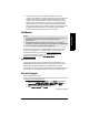
Allowable operating area of SITRANS LR560 Loop Voltage versus Loop Resistance Operation with HART Startup Behavior • • The device draws less than 3.6 mA at startup. Time to first measurement is 60 seconds nominal.
F: HART Communications mmmmm Appendix F: HART Communications Highway Addressable Remote Transducer, HART, is an industrial protocol that is superimposed on the 4-20 mA signal. It is an open standard, and full details about HART can be obtained from the HART Communication Foundation at www.hartcomm.org SITRANS LR560 can be configured over the HART network using either the HART Communicator 375 by Emerson, or a software package.
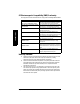
Note: HART Communicator 375 is supported by SITRANS LR560 HART. The menu structure is aligned with the menu structure of SIMATIC PDM. 1 Configure/Setup 1 Identification 1 Identification 1 Long Tag 2 Tag 3 Descriptor 4 Message 5 Date 6 Range Mode 2 Device 1 Manufacturer 2 Product Name 3 Order Number 4 Final Assembly num 5 Hardware Revision 6 Firmware Revision 7 Loader Revision 8 EDD Version: xx.xx.
F: HART Communications mmmmm 3 High Calibration Point (Y) 4 Response Rate 5 Tank Image 4 Step 4 - Summary 1 Identification 1 Long Tag 2 Tag 3 Descriptor 4 Message 5 Installation Date 6 Order Number 7 Range Mode 8 Language 2 Application 1 Application Type 2 Operation 3 Ranges 1 Unit 2 Low Calibration Po… 3 High Calibration P… 4 Response Rate 2 Configuration Flag Reset 1 Configuration Flag Reset 2 Device Status Icon 3 Operation 1 General 1 Select Analog Output 2 Master Reset 2 Simulation / Test 1 Self Tes
3 Sampling 4 Echo Quality 5 Filtering 2 TVT 6 Device Status Icon 1 TVT Setup 4 Local Display 1 Language 2 LCD Contrast 3 LCD Backlight 4 Device Status Icon 1 Algorithm 2 Position Detect 3 Echo Threshold 4 CLEF Range 5 Echo Marker 1 Echo Lock 2 Sampling Up 3 Sampling Down 4.
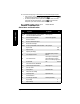
F: HART Communications mmmmm 4 Activation of Reminders 5 Reminder 1 before Lifetime (Required) 6 Reminder 2 before Lifetime (Demanded) 7 Sensor Replaced 8 Snooze for 1 Year 9 Device Status Icon 3 Service Schedule 1 Service Interval 2 Time Since Last Service 3 Time Until Next Service 4 Activation of Reminders 5 Reminder 1 before Service (Required) 6 Reminder 2 before Service (Demanded) 7 Service Performed 8 Device Status Icon 4 Calibration Schedule 1 Calibration Interval 2 Time Since Last Calibration 3 Tim
2 Analog Output 1 Primary 2 PV: Distance 3 Secondary 4 SV: Distance 5 Device Status Icon 1 Distance Range [%] 2 Analog Output [mA] 3 Device Status Icon 3 Trend View 1 Trend Values 1 Primary 2 Secondary 2 Trend View 3 Device Status Icon HART Version SITRANS LR560 conforms to HART rev. 6. Burst Mode SITRANS LR560 does not support burst mode. HART Multidrop Mode We do not recommend the use of HART Multidrop Mode.
Firmware Rev. EDD Rev. 1.00.00 1.00.
Glossary accuracy: degree of conformity of a measure to a standard or true value. algorithm: a prescribed set of well-defined rules or processes for the solution of a problem in a finite number of steps. ambient temperature: the temperature of the surrounding air that comes in contact with the enclosure of the device. antenna: an aerial which sends out and receives a signal in a specific direction. There are four basic types of antenna in radar level measurement, horn, parabolic, rod, and waveguide.
dielectric constant is directly proportional to an increase in signal amplitude. The value is usually given relative to a vacuum /dry air: the dielectric constant of air is 1. echo: a signal reflected with sufficient magnitude and delay to be perceived as a signal distinct from that are directly transmitted. Echoes are frequently measured in decibels relative to the directly transmitted signal. Echo confidence: describes the quality of an echo. Higher values represent higher quality.
parameters: in programming, variables that are given constant values for specific purposes or processes. polarization: the property of a radiated electromagnetic wave describing the time-varying direction and amplitude of the electric field vector. polarization error: the error arising from the transmission or reception of an electromagnetic wave having a polarization other than that intended for the system. propagation factor (pf): where the maximum velocity is 1.
Index A Abbreviations and Identifications list 4 access control remote access 110 activating LR560 26 agitator blade detection avoiding 91 AMS Device Manager features 54 analog output explanation 128 fail signal 8 load 8 select 49 signal range 8 simulate via PDM 49 approvals 10 Auto False Echo Suppression 126 explanation 126 setup 94 setup via PDM 46 B blanking (see Near Range) 127 Index mmmmm C cables requirements 22 Calibration Interval 107 cleaning instructions 121 communication load 8 max.
handheld programmer edit mode 30 measurement mode 28 navigation 30 HART device description 134 multidrop mode 139 HART communication set preambles 50 HART Communications details 134 HART version 8 hazardous area installations wiring requirements 24 see Calibration Interval 107 see Remaining Sensor Lifetime 101 see Service Interval 104 Master Reset factory defaults 103 factory defaults via AMS 55 measurement range blanking via Near Range 127 extension via Far Range 127 Measurement Response explanation 128 m
Response Rate explanation 128 settings 82 S Scan Device synchronize parameters via AMS 56 security password protection via AMS 68 password protection via PDM 52 remote access control 110 remote access control via AMS 66 self-test device self-test via PDM 49 settings adjust parameters via LUI 30 SIMATIC PDM Quick Start 39 simulate analog output loop test 49 specifications 7 ambient temperature 9 antenna 8 enclosure 8 environmental 9 performance 7 power 7 pressure 9 process connections 8 process temperature
Appendix C: menu chart LCD menu structure SITRANS LR560 (HART) – INSTRUCTION MANUAL Page 147 SITRANS LR560 (HART) – INSTRUCTION MANUAL 7ML19985KB01
Appendix C: menu chart LCD menu structure Notes: • In Navigation mode ARROW keys navigate the menu in the direction of the arrow.. • See See Parameter Reference on page 76. for detailed information and instructions. 1. WIZARDS 1.1 QUICK START WIZ VESSEL RESPONSE RATE UNITS OPERATION LOW CALIB. PT. HIGH CALIB. PT. 1.2 AFES WIZ 1.3 COPY PARAMETERS TO DISPLAY 1.4 COPY PARAMETERS FROM DISPLAY 1.5 COPY FIRMWARE TO DISPLAY 1.6 COPY FIRMWARE FROM DISPLAY 2. SETUP 2.1 DEVICE 2.1.1 LONG TAG 2.1.2 TAG 2.1.
3. DIAGNOSTICS 3.1 3.2 3.3 3.4 4. SERVICE 4.1 4.2 4.3 4.4 4.5 4.6 4.7 DEMO MODE MASTER RESET POWERED HOURS POWERON RESETS LCD BACKLIGHT LCD CONTRAST SERVICE SCHEDULE 4.7.1 TIME LAST SERV 4.7.2 TIME NEXT SERV 4.7.3 REMINDER 1 (REQ) 4.7.4 REMINDER 2 (DEM) 4.7.5 REMINDER ACTIVATION 4.7.6 SERVICE INTERVAL 4.7.7 MAINT STAT 4.7.8 ACK STATUS 4.7.9 ACK 4.8 CALIB. SCHEDULE 4.8.1 TIME LAST CALIB 4.8.2 TIME NEXT CALIB 4.8.3 REMINDER 1 (REQ) 4.8.4 REMINDER 2 (DEM) 4.8.
4.8.6 4.8.7 4.8.8 4.8.9 CALIB INTERVAL MAINT STATUS ACK STATUS ACK 5. COMMUNICATION 5.1 DEVICE ADDRESS 5.2 REMOTE LOCKOUT 6. SECURITY 6.1 WRITE PROTECTION LCD menus mmmmm 7.
www.siemens.com/processautomation For more information www.siemens.com/level www.siemens.com/continuous-weighing Siemens Milltronics Process Instruments Inc. Industry Automation (IA) 1954 Technology Drive P.O. Box 4225 Peterborough, ON Canada K9J 7B1 Subject to change without prior notice 7ML19985KB01 Rev. 1.0-03 © Siemens Milltronics Process Instruments Inc. 2010 email: techpubs.smpi@siemens.com www.siemens.