
User's Manual
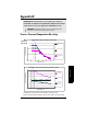
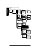
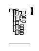
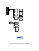
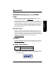
Table Of Contents

7ML19985FH04 SITRANS LR 400 – INSTRUCTION MANUAL Page 94
mmmmm
Appendix V
Chart 2
1. Tank geometry
2. Measuring conditions
3. Sensor parameters
4. Level parameters
5. Volume parameters
6. Mass parameters
1. Nozzle height
2. Tank height
3. Stilling pipe?
Operating Parameters Tank Geometry
1. Application type
2. Surface
3. Dead band
4. Correction factor
5. Filling speed
6. Failsafe level
7. Failsafe timer
8. Range extension
Measuring Conditions
1. Sensor damping
2. Multiple echo
3. Echo motion
4. Window tracking
5. Tank empty detection
6. Auto fix distance
7. Fix distance list
8. Echo suppress.
9. Echo suppress dist.
Sensor parameters
1. URV
2. LRV
3. Damping
4. Min limit
5. Max limit
6. HYST
Level Parameters
1. Volume URV
2. Volume LRV
3. Volume damping
4. MinLim Volume
5. MaxLim Volume
6. HYST Volume
7. Tank characteristic
8. Calibrate/table
or Calculate
Volume Parameters
1. Calibrate
2. Enter table
3. Show table
4. Clear table
Calibrate/table
1. Tank design
2. Bottom design
3. Tank volume
calculate
1. Liquid (store)
2. Liquid (process)
3. Silo1 (solids)
4. Silo2 (solids)
5. User tank1
6. User tank2
Application type
1. smooth
2. wavy
3. turbulent
Surface
1. 100%
2. 0%
3. Hold continuously
Failsafe Level
1. Off
2. Record
3. Use
False Echo Suppression
1. Mass URV
2. Mass LRV
3. Mass damping
4. MinLim Mass
5. MaxLim Mass
6. HYST Mass
7. Tank characteristic
8. Calibrate/table
or Calculate
Mass Parameters
1. Calibrate
2. Enter table
3. Show table
4. Clear table
Calibrate/table
1. Tank design
2. Bottom design
3. Tank volume
calculate