
User's Manual
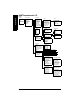
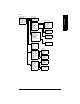
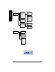
Table Of Contents

Page 93 SITRANS LR 400 – INSTRUCTION MANUAL 7ML19985FH04
mmmmm
Appendix V
HART Communicator 275:
Chart 1
1. Level
2. AO
3. Device Setup
4. Refresh
1. Auto-Setup
2. Display
3. Diagnostics
4. Device Data
5. Options
6. Review
1. Language Local
2. Length Unit
3. Nozzle Height
4. Tank Height
5. Level URV
6. Level LRV
7. Level Damping
8. Application Type
1. Level
2. Volume
3. Mass
4. AO
5. DO
1. Status
2. Device Test
3. Simulation
4. Sensor Variables
1. Units
2. Operating parameters
3. Output parameters
4. Display param (local)
5. Device information
6. HART info
1. Local keys ctrl mode
2. Customer code
3. Factory reset
On Line Device Setup Auto-Setup
Display
Diagnostics
Device Data
Options
1. Wear
2. Sensor Status
3. Electronic Status
4. Software Status
5. Application Status
6. Parameter Info
7. Service Info
Status
1. Operating hours
2. Maximum temp
3. Min temp
4. Aging
5. Hours > 85°C
Wear
1. Self-test
2. Local display test
3. Master reset
Device Test
1. Simulate AO
2. Simulate DO
Simulation
1. 4 mA
2. 20 mA
3. Other
4. End
Simulate AO
1. Relay on
2. Relay off
3. End
Simulate DO
1. Raw Value
2. Echo Amplitude
3. S/N Ratio
4. Validity
5. Sens Temp
Sensor Variables
1. Length unit
2. Volume unit\
3. Mass unit
4. Temp unit
5. Other unit
Units
Operating Parameters (see Chart 2)
Output Parameters (see Chart 3)
Display Parameters (see Chart 4)
1. Power supply
2. Process temp
3. Electrical connection
4. Local meter
5. Antenna and flange
6. Tag descriptor
7. Message
8. Last config
9. Manufacturer data
Device information
1. Manufacturer
2. Model
3. HART Dev. I.D.
4. Universal Rev.
5. Fld. dev. rev.
6. Software rev.
7. Hardware rev.
HART info
1. Serial number
2. Device order number
3. Actual order number
4. Software version
5. Hardware version
6. Antenna offset
7. Reference distance
Manufacturer Data
1. Flange size
2. Flange type
3. Pressure range
4. Antenna type
5. Antenna extension
6. Flange material
7. Seal material
Antenna and Flange