
User's Manual
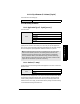
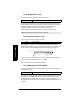
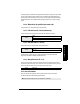
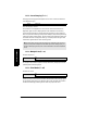
Table Of Contents

Page 47 SITRANS LR 400 – INSTRUCTION MANUAL 7ML19985FH04
mmmmm
Parameters (HART)
4.2.3.9: Auto False Echo Suppression Distance (F = 2/3 tank
height)
Defines the end point of the auto false echo suppression distance
4.2.3.A: Hover Level (F = 40%)
Defines (in percent) how high the TVT (Time Varying Threshold) curve is placed above the
profile, relative to the largest echo. When SITRANS LR 400 is located in the center of the
vessel, lower this parameter to prevent multiple echo detections.
4.2.3.B: Window Trigger (F = 80%)
Defines the position of the window on the leading edge of the selected echo, relative to
the amplitude. Used only on Silo1 and Silo2 applications (see Application Type on
page 35).
4.2.4: Level Parameter
4.2.4.1: Level URV (F = 20 m)
Full scale of level (see Functional Dimensions on page 33)
Set the URV as the level above the bottom of the vessel (see Functional Dimensions on
page 33) in the units system selected with Parameter 4.1.1. It corresponds to an output
current of 20 mA.
4.2.4.2: Level LRV (F = 0 m)
Empty scale of level (see Functional Dimensions on page 33)
Set the LRV as the level above the bottom of the vessel (see Functional Dimensions on
page 33) in the units system selected with Parameter 4.1.1. It corresponds to an output
current of 4 mA.
Value variable
Values Range: 0 to 100%
Values Range: 0 to 100%
Value numerical value
Note: This parameter is also set using Parameter 1.5 (Level URV).
Value numerical value
Note: This parameter is also set using Parameter 1.6 (Level LRV).