
User's Manual


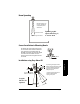
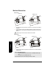
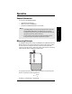
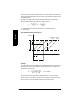
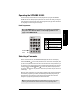
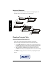
Table Of Contents

7ML19985FH04 SITRANS LR 400 – INSTRUCTION MANUAL Page 19
mmmmm
Installation
Beam Spreading
Correct Installation in Mounting Nozzle
The bottom edge of the antenna must project
into the vessel to avoid reflective interference
at the wall of the nozzle. Above flange size
DN 150/6", the antenna need not project beyond
the nozzle unless the radiation cone (the
extension of the antenna’s angle) touches the
nozzle wall.
Installation using Easy Aimer LR
SITRANS LR 400
13°
9°
Keep the emission cone
(9° or 13° depending on
configuration), free of
obstructions.
short horn antenna
long horn antenna
Updated graphic
required showing 2",
3" and 4" horn
SITRANS LR 400
10 mm
top clamping plate (upper socket)
bottom clamping plate (lower socket
)
customer gasket [recommended
thickness 1.5 to 1.8 mm (0.06 to
0.07")], as required
customer mounting plate with at
least ø 4" (102 mm) central
opening, as required
30°
max.
long horn 9.3"(235 mm)
short horn 7.4"(188 mm)
0.38"
(10 mm)
Graphic
labels to be
updated