
User's Manual
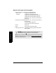
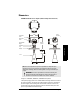
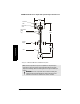
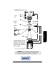
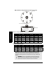
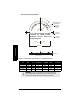
Table Of Contents

Page 14 SITRANS LR 400 – INSTRUCTION MANUAL 7ML19985FH04
mmmmm
Specifications
DIN / JIS Flat Face Flange Diagram (for Liquids version only)
Flange according to DIN 2527 (see Flange Diagram above)
Flange according to JIS B 2238
Pipe Size
Flange
Size
Flange
O.D.
Thickness
(s)
Bolt Hole
Circle Ø
Bolt Hole
Ø
Number of
Bolts
80 mm PN 16 200 mm 20.0 mm 160 mm 18.0 mm 8
100 mm PN16 220 mm 20.0 mm 180 mm 18.0 mm 8
150 mm PN 16 285 mm 22.0 mm 240 mm 22.0 mm 8
80 mm PN 40 200 mm 24.0 mm 160 mm 18.0 mm 8
100 mm PN 40 235 mm 24.0 mm 190 mm 22.0 mm 8
150 mm PN 40 300 mm 28.0 mm 250 mm 26.0 mm 8
Pipe Size
Flange
Size
Flange
O.D.
Thickness
(s)
Bolt Hole
Circle Ø
Bolt Hole Ø
Number of
Bolts
80 mm 10 K 185 mm 20.0 mm 150 mm 19.0 mm 8
100 mm 10 K 210 mm 22.0 mm 175 mm 19.0 mm 8
150 mm 10 k 280 mm 24.0 mm 240 mm 23.0 mm 8
Note: Process temperature and pressure capabilities are dependent upon
information on the process device tag. See Appendix IV (Process Pressure/
Temperature de-Rating). Reference drawing listed on the tag is available upon
request.
WARNING: The user is responsible for the selection of bolting and
gasket materials which will fall within the limits of the flange and its
intended use and which are suitable for the service conditions.
bolt hole
Ø
thickness (s)
flange O.D.
bolt hole circle Ø
horn mounting holes