
User's Manual
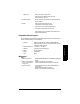
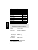
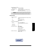
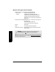
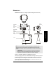
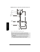
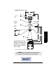
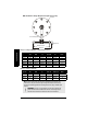
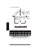
Table Of Contents

7ML19985FH04 SITRANS LR 400 – INSTRUCTION MANUAL Page 11
mmmmm
Specifications
Dimensions
SITRANS LR 400 Version for Liquids (without Temperature Extension)
*Flange acc. to DIN 2527 / ANSI B16.5 / JIS B2238 bolt hole pattern
**An optional purging system can be installed between the flange and the horn antenna.
The system provides a 1/8” NPT inlet on the flange where cooling air or cleaning fluid
passes through the universal flange and exits the inside of the horn to clean it. The
customer will supply the purging medium by manual or automatic valve system. This
option is only available with universal flanges.
SITRANS LR 400
Note: Process temperature and pressure capabilities are dependent upon
information on the process device tag. See Appendix IV (Process Pressure/
Temperature de-Rating). Reference drawing listed on the tag is available upon
request.
WARNING: The user is responsible for the selection of bolting and
gasket materials which will fall within the limits of the flange and its
intended use and which are suitable for the service conditions.
204 mm
(8.0")
281 mm
(11.1")**
191 mm
(7.5")
238 mm
(9.4")
74 mm
(2.9")
93 mm
(3.7")
horn
process
flange*
threaded
ring
intermediate
flange
electronics
cover
connection
cover
earth
terminal