Instruction Manual October 2004 sitrans LR 400
Safety Guidelines: Warning notices must be observed to ensure personal safety as well as that of others, and to protect the product and the connected equipment. These warning notices are accompanied by a clarification of the level of caution to be observed. Qualified Personnel: This device/system may only be set up and operated in conjunction with this manual. Qualified personnel are only authorized to install and operate this equipment in accordance with established safety practices and standards.
Table of Contents General Information ........................................................................................................... 1 Safety Notes .............................................................................................................................................1 The Manual ...............................................................................................................................................1 Abbreviations and Identifications ..................
Self-test ....................................................................................................................................................75 Symptoms, Causes and Their Remedy ............................................................................................75 Fault Messages .....................................................................................................................................76 Unit Repair and Excluded Liability ....................................
General Information Safety Notes Special attention must be paid to warnings and notices highlighted from the rest of the text by grey boxes. CAUTION: means that failure to observe the necessary precautions can result in considerable material damage. Note: means important information about the product or that part of the operating manual.
This manual will help you set up your SITRANS LR 400 for optimal performance. We alwasy welcome suggestions and comments about manual content, design, and accessibility. Please direct your comments to techpubs.smpi@siemens.com. For the complete library of Siemens Milltronics manuals, go to www.siemens.com/processautomation WARNINGS: General Information mmmmm • Installation shall only be performed by qualified personnel and in accordance with local governing regulations.
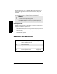
SITRANS LR 400 The SITRANS LR 400 is a long-range FMCW radar level instrument. A liquids version (L) is available for use in liquids storage, performing well on low dielectric liquids or sticky materials requiring a purging unit. A solids version (S) incorporates the Easy Aimer design for use in solids, especially conditions of extreme dust. On both versions, the narrow antenna beam results in a sharp radiation cone, which makes the SITRANS LR 400 quite insensitive to vessel interferences.
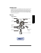
Solids Version housing cable gland connection cover General Information mmmmm electronics cover display module intermediate flange device tag process flange hand programmer (ordered separately) threaded ring horn antenna Arrows required The terminals for the power cable and the signal cable are behind the connection cover on the left side of the housing. The signal cable must be fed in from the right through the cable glands.
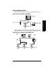
System Implementation SITRANS LR 400 supports HART communication protocol, and SIMATIC PDM software. Typical PLC/mA configuration with HART PLC with mA input card HART PC/laptop with HART modem running PDM S I TR A N S L R 4 0 0 Note: A 250 ohm loop resistor may be required, depending on PLC input resistance.
Specifications Note: Siemens Milltronics makes every attempt to ensure the accuracy of these specifications, but reserves the right to change them at any time. Please ensure these are the most recent specifications. Contact your representative, or check our web site at www. siemens.com/milltronics for the most up-to-date information.
Signal type Relay, either NCC or NOC function max. 50 V DC, max. 200 mA, rating max. 5 W.
Weight • Weight of instrument and flange Process Connection Specifications mmmmm Universal, 2" / 50 mm, flat faced, 0.5 bar maximum Universal, 3" / 80 mm, flat faced, 0.5 bar maximum Universal, 4" / 100 mm, flat faced, 0.5 bar maximum Universal, 6" / 150 mm, flat faced, 0.
• Electromagnetic compatibility Spurious emission according to EN 50 081 Interference strength according to EN 50 082 • Perm. ambient -40 to 65 °C (-40 to 149 °F) (non-hazardous version) temperature LCD: -10 to 55 °C (14 to 131 °F) Observe the temperature classes in hazardous areas! WARNING: Materials of construction are chosen based on their chemical compatibility (or inertness) for general purposes. For exposure to specific environments, check with chemical compatibility charts before installing.
Approvals (verify against device nameplate) • Explosion Protection (Liquids)Certificate No. PTB 00 ATEX 1024 *Refer to device II 1/2G EEx d IIC T6II 2G EEx d IIC T6 nameplate II 1/2G EEx dem IIC T6II 2G EEx dem IIC T6 II 1/2G EEx dem [ib] IIC T6II 2G EEx dem [ib] IIC T6 II 1/2G EEx dem [ia] IIC T6II 2G EEx dem [ia] IIC T6 FM/CSA Class I, Div. 1, Groups B, C, D; Class II/III, Div. 1, Groups E, F, G • Explosion Protection (Solids)FM/CSA Class II, Div. 1, Groups B, C,D; Class II/III, Div.
Dimensions SITRANS LR 400 Version for Liquids (without Temperature Extension) 204 mm (8.0") earth terminal connection cover electronics cover SITRANS LR 4 00 281 mm (11.1")** 191 mm (7.5") 238 mm (9.4") horn 74 mm (2.9") 93 mm (3.7") Note: Process temperature and pressure capabilities are dependent upon information on the process device tag. See Appendix IV (Process Pressure/ Temperature de-Rating). Reference drawing listed on the tag is available upon request.
SITRANS LR 400 Version for Liquids with optional Temperature Extension 204 mm (8.0") connection cover electronics cover SITRANSLR 400 intermediate flange threaded ring 384 mm (15.1") Specifications mmmmm process flange* 191 mm (7.5") 238 mm (9.4") horn 74 mm (2.9") 93 mm (3.7") *Flange acc. to DIN 2527 / ANSI B16.5 / JIS B2238 bolt hole pattern Note: Process temperature and pressure capabilities are dependent upon information on the process device tag.
SITRANS LR 400 Version for Solids 204 mm (8.0") connection cover electronics cover SITRANS LR 400 intermediate flange threaded ring 285 mm (11.2") 412 mm (16.2") with temperature extension Easy Aimer Flange* horn 74 mm (2.9") Graphic labels to be updated. New graphic to be included for Optional Horn Extension and dust cover version 93 mm (3.7") *Flange acc. to DIN 2527 / ANSI B16.
DIN / JIS Flat Face Flange Diagram (for Liquids version only) bolt hole Ø horn mounting holes thickness (s) bolt hole circle Ø flange O.D. Specifications mmmmm Flange according to DIN 2527 (see Flange Diagram above) Pipe Size 80 mm 100 mm 150 mm 80 mm 100 mm 150 mm Flange Size PN 16 PN16 PN 16 PN 40 PN 40 PN 40 Flange O.D. 200 mm 220 mm 285 mm 200 mm 235 mm 300 mm Thickness (s) 20.0 mm 20.0 mm 22.0 mm 24.0 mm 24.0 mm 28.
ANSI Raised Face Flange Diagram (for Liquids version only) bolt hole Ø horn mounting holes thickness (s) raised face thickness 0.063" (mm) Pipe Size 3" 4" 6" 3" 4" 6" Flange Flange Thickness Size O.D. (s) 150 # 7.50" 0.941" 150 # 9.00" 0.941" 150 # 11.00" 1.00" 300 # 8.25" 1.12" 300 # 10.00" 1.25" 300 # 12.51" 1.44" Face O.D. 5.0" 6.19" 8.5" 5.0" 6.19" 8.5" Bolt Hole Circle Ø 6.00" 7.50" 9.50" 6.62 7.88" 10.62" Bolt Hole Ø 0.75" 075" 0.88" 0.88" 0.88" 0.
Universal Slotted Flange Diagram 45° only available on pipe size 8" (200 mm) number of slotted bolt holes A New Univeral Flange graphic required for Solids version. Replaces current Universal Flange diagram. A bolt hole circle max Ø bolt hole circle min Ø Specifications mmmmm flange O.D. thickness section A-A Flange according to Universal Slotted Flange (see Flange Diagram above) Pipe Flange ThickBolt Hole Bolt Hole Bolt Hole Number of Size O.D.
Purging System For more frequent cleaning, a purging system can be installed between the flange and the horn antenna. The system provides an inlet on the flange where cooling air or cleaing fluid passes through the flange and exits the inside of the horn to clean it. The customer will supply the purging medium by manual or automatic valve system. This option is only available with universal flanges on the Liquids version of the SITRANS LR 400.
Installation Notes: • The SITRANS LR 400 is rated for Type 4X/NEMA 4X, Type 6/NEMA 6, IP67. Follow all installation and operating instructions to meet the requirements of this type of protection. Use only approved, suitable sized hubs for watertight applications. • Observe all maximum permissible ambient and process temperatures. Refer to Appendix III (Ambient/Operating Temperature Specification).
Beam Spreading ST I R ANSL R400 Keep the emission cone (9° or 13° depending on configuration), free of obstructions. 13° short horn antenna 9° long horn antenna Updated graphic required showing 2", 3" and 4" horn Correct Installation in Mounting Nozzle The bottom edge of the antenna must project into the vessel to avoid reflective interference at the wall of the nozzle.
Electrical Connection AC version: HART wiring PROFIBUS wiring earth terminal cable clamp 3 4 5 6 7 8 1 2 Rated temperature of connection cables must exceed maximum ambient temperature by at least 15 K mA • earth terminal cable clamp 3 4 5 6 7 8 1 2 L1 L2 N L1 L2 Rated temperature of connection cables must exceed maximum ambient temperature by at least 15 K PROFIBUS PA N The equipment must be protected by a 15A fuse or circuit breaker in the building installation.
Connecting the SITRANS LR 400: 1. 2. 3. Release the cover lock on the connection box with a 3 mm Allen key. Unscrew the cover from the connection box. Push the power cable and signal cable through the cable gland on the right of the unit, up to the terminal strip. Lay the cable in a bend before the cable gland so that moisture cannot enter the connection box. 4. Connect the earth conductor of the power supply to the earth terminal in the connection box.
Start Up mmmmm Start Up Self-test The device performs a self-test after power is supplied. Then, the unit is ready for programming when the multi-display appears. Note: Frequent switching off and on of the device causes aging of the electronics (see Parameter 3.1). Multi-display The multi-display shows on the LCD after a successful self-test with the output of the level in the first line and the signal-to-noise ratio in the second line (factory setting): + 1 2 .
Operation General Information You can operate the SITRANS LR 400 with: • • • Hand-held infrared programmer HART Communicator or PROFIBUS PA PC/Laptop and SIMATIC PDM software (recommended) Notes: • The SITRANS LR 400 operates according to the FMCW (Frequency Modulated Continuous Wave) method. Its antenna sends microwaves to the surface of the measuring medium. The wave frequency is modulated continuously (see Determining the Differential Frequency on page 25).
As the transmission signal has changed its frequency until the reception signal arrives, the linked signal gives a differential frequency fd, which is proportional to the distance d from the reflecting surface.
Operating the SITRANS LR 400 Use the arrow keys at the bottom of the hand programmer to program the SITRANS LR 400. The two-line LCD displays the parameters. You can alter the setting or change to other parameters using the arrows on the hand programmer (see page 27 for information on navigating the menus using the arrow keys). Hand Programmer Note: The ARROW buttons shown below are required for programming this product. The additional buttons on the hand programmer do not apply to the SITRANS LR 400.
Structure of Parameters Operation is hierarchically structured: the parameters are arranged in groups and assigned a numerical menu identification (see example below). 2. Display 1 Multi-display 2. Display 2 Level 2. Display 3 Volume Op Function group 3 Diagnostics 4. Device Data 1 Units 4. Device Data 2 Operating parameters 4. Device Data 3 Analog output 4. Device Data 3 Digital output 4.4 Digital output 1 Function DO 4.4 Digital output 2 Signal type DO 4.
Entering a Parameter Value The ARROW keys operate like a cursor control when entering a parameter value with the input position marked by flashing of a single character. • • • Increase or decrease a character’s value by using UP and DOWN . Press RIGHT to move the input position to the right. At the far right position, press RIGHT again: operates like an ENTER key. The device saves the changed value and closes the parameter unless the value is not within the permissible input range.
Disabling and Enabling Programming To prevent unauthorized personnel causing programming errors through the display module, set a customer code – a personal, freely selectable code number up to 9 digits. A device protected by a customer code still displays all functions and values but it requests input of the code number before allowing a parameter to be reset. Note: The customer code is activated 10 minutes after you have programmed Parameter 5.2 Customer Code.
Operating Examples Example 1(HART) The length unit should be changed from m to mm. The starting point is the multi-display. Function group 1 Auto-Setup 1 +12,300 m +30 dB Function group 2 Display 4. Device data 1 Units 4.1 Units 1 Length Unit 4.1.1 Length unit m 4.1.1 Length unit mm 4. Device data 2. Operating param. 4. Device data 3 Analog output 4.3 Analog output 1 AO select 4.3.1 AO select Level 4.3 Analog output 2 Level param. 4.3.2 Level param.
Example 2 The filling speed should be changed from 2.0 cm/min to 100 cm/min. Access the Fill speed parameter from the multi-display according to instructions on page 27. Enable the programming. The second segment of the second display line flashes. Operation mmmmm The default setting appears in the display. i n g s p e e 4. 2. 2. 5. f i l l + 2. 0 0 c m / m i n 4. 2. 2. 5. f i l l i n g s p e e c m / m i n + 2 , 0 0 1x Set the digit to 1 with DOWN arrow. f i l l 4. 2. 2. 5.
Parameters (HART) The parameter groups are followed by the parameters within each group. The parameter tables show the values you need to enter and are followed by additional information when necessary. Factory settings are displayed after the parameter name, where applicable. Note: Parameter menus are dependent on selections made by the user. In some cases, parameter menus are renumbered according to the selection made at the previous menu level. See table below for an example. 4.2.2.
Functional Dimensions 1 SI TRAN SLR 40 0 1. Nozzle height 2. Dead band 3. Raw value (measured) 4. Level (=calculated value) 5. Lower range value 6. Lower limit 7. Upper limit 8. Upper range value 9. Vessel height 2 3 9 8 7 4 6 Parameters (HART) mmmmm 5 Required Parameters Note: The following parameters are absolutely essential for proper operation of the device. They apply to all applications and are required to make the system operational. 1. Auto-Setup 1.
1.2: Length Unit (F = m) Units of measurement Value cm m mm ft in 1.3: Nozzle Height (F = 0 m) Length of nozzle from top of flange to top of vessel (see Functional Dimensions on page 33) Value numerical value 1.4: Tank Height (F = 20 m) Height of vessel from bottom of nozzle to bottom of vessel (see Functional Dimensions on page 33) numerical value 1.
1.7: Level damping (F = 1 s) Damping of level in s Value numerical value Set the damping of the level value in seconds. It acts on the analog output, the limit value monitor and the local display. For damping of the sensor signal, set Parameter 4.2.3.1. For slow moving solids applications, use a value of 500. 1.
2.3: Volume (F = m3) Volume of measured medium (set unit using Parameter 4.1.2 [Volume Unit]) 2.4: Mass (for qualified personnel only) This parameter is for Factory Authorized Personnel Only. 2.5: Current Output Value of the analog output in mA When the device electronics are working properly, the displayed current value will correspond to the measured output current. 2.6: Digital Output State of digital output 3. Diagnostics 3.1.1: Wear 3.1.1.
This parameter outputs a calculated percentage which estimates the wear of the device due to aging. 3.1.1.5: Hours > 85 °C Total time the maximum permissible internal temperature was exceeded, in hours 3.1.x: Sensor, electronics, software, application, parameters, service These parameters are only displayed if they contain an error message. The number of the menu items matches the number of defective functions and can range in extreme cases from 3.1.2 to 3.1.7.
3.2: Device Test 3.2.1: Self-test Check device state The device integrates the self-test routines in the ongoing measurements; it completes them after approximately 10 seconds. It confirms a successful self-test with the display OK . The display not OK signals an error. Read out the error type according to Parameter 3.1.x. 3.2.
3.3.2: Simulate DO (F = End) Simulation of the digital output signal Relay on Relay off End Value Select the applied output value (relay on or relay off). The parameter function is completed by pressing LEFT gives an alarm/limit. so that the digital output again 3.4: Sensor Variables You can read out device-internal data with this parameter group. The displayed values depend on the respective application. You can access the following data: 3.4.
3.4.4: Validity Validity of the measured value in % This parameter provides a percentage measure of the certainty that the displayed measured value corresponds to the real level and does not represent a multiple echo or a fixed target. Its display can be evaluated as follows: • • • • x > 70: 70 > x > 50: 50 > x > 20: x < 20: very good good uncertain no plausible measured value 3.4.5: Sensor Temp Sensor temperature 4. Device Data 4.1: Units 4.1.
4.1.4: Temperature Unit (F = °C) Unit of the sensor temperature °C °F K Value 4.1.5: Other units (F = SI) Units system for all other units SI unit US/UK unit Value With this function, determine whether you want to enter the operating parameters (see Parameter 4.2) in SI or in British Imperial (US/UK) units. The selected units of the measured value output and sensor temperature as well as the decimal point are not influenced by this setting. Parameters (HART) mmmmm 4.
4.2.1.3.2: Pipe Diameter (F = 100 mm) [Liquids] Internal diameter of the stilling pipe Value numerical value 4.2.2: Measuring Conditions 4.2.2.1: Application Type (F - Liquid [process]) Use of the vessel Value Liquid (store) [Liquids] Liquid (process) [Liquids] Silo1 (solids) Silo2 (solids) User tank1 User tank2 Parameter 4.2.2.2 (Surface), Parameter 4.2.2.5 (Filling Speed), Parameter 4.2.2.6 (Reflectivity), and Sensor Parameters 4.2.3.1 (Sensor Damping), 4.2.3.2 (Multiple Echoes), 4.2.3.
4.2.2.3: Dead band (F = 0.4 m) Area below the flange in which measured values are ignored Value numerical value, Minimum value = Length of the antenna Specification of a dead band in the units system selected according to Parameter 4.1.5 defines a minimum distance from the flange which the measuring medium must have for the device to accept the measured values as valid. This suppresses reflective interference generated by the nozzle, close obstacles, or the antenna.
If the display does not follow the level height continuously but in abrupt jumps, you should choose a higher filling speed. If multiple echoes are indicated during filling/emptying a vessel, select a lower filling speed. In the case of very low filling speeds (a few mm/min) switch off Parameter 4.2.3.3. If different filling/emptying speeds occur, select the higher speed. 4.2.2.6: Reflectivity (for qualified personnel only) This parameter is for Factory Authorized Personnel Only. 4.2.2.
4.2.3.1: Sensor Damping (F = 1 s) Averaging of measuring signal. Not displayed if a user vessel is selected in Parameter 4.2.2.1 (Application Type). Value numerical Enter the damping in seconds. This parameter is not displayed when a user vessel is selected in Parameter 4.2.2.1 (Application Type). The sensor damping influences the evaluation of the measuring signal.
4.2.3.4: Window Tracking (F = Off) Value On Off A window follows the measured value which it is forced to track. The window size is calculated from the set filling speed. Switch off window tracking for applications where the SITRANS LR 400 is unable to keep up to level changes. By using SIMATIC PDM, you can display a list of all echoes in your vessel. It provides the distance between the flange and the measuring medium’s surface, as well as the distances of fixed targets.
4.2.3.9: Auto False Echo Suppression Distance (F = 2/3 tank height) Defines the end point of the auto false echo suppression distance Value variable 4.2.3.A: Hover Level (F = 40%) Defines (in percent) how high the TVT (Time Varying Threshold) curve is placed above the profile, relative to the largest echo. When SITRANS LR 400 is located in the center of the vessel, lower this parameter to prevent multiple echo detections. Values Range: 0 to 100% 4.2.3.
4.2.4.3: Level damping (F = 1 s) Damping of level in s Value numerical value Set the damping of the level value in seconds. It acts on the analog output, the limit value monitor and the local display. For damping of the sensor signal, set Parameter 4.2.3.1. Note: This parameter is also set using Parameter 1.7 (Level Damping). 4.2.4.
4.2.5: Volume Parameters To calculate the volume of the measuring medium, you need the level parameters (Parameter 4.2.4) in the units selected according to Parameter 4.1.1 and additionally a tank characteristic (Parameter 4.2.5.7). 4.2.5.1: Volume URV (F = 20 m3) Full scale of volume Value numerical value 4.2.5.2: Volume LRV (F = 0 m3) Start of scale of volume Value numerical value 4.2.5.3: Volume Damping (F = 1 s) Parameters (HART) mmmmm Damping of volume Value numerical value 4.2.5.
Note: Select the option Calibrate/table or Calculate as required. The selection controls the display of Parameter 4.2.5.8. The possibilities of each parameter are listed below. For the values associated with Parameter 4.2.5.8: Calculate, go to page 51. 4.2.5.8: Calibrate/table If your vessel deviates from the forms offered, the necessary data is not available or is unknown, or you need a vessel characteristic with greater accuracy, you will need to use a level/volume calibration table.
The first reference value is offered when you access the parameter. Enter the level as a distance from the floor of the vessel in the units selected according to Parameter 4.1.1 (Enter level) and the volume corresponding to the level (Enter volume). The device then displays Enter table again. Access again to enter a further reference value. The device automatically offers you the next undefined reference value.
4.2.5.8.1: Tank Design (F = Vertical Cylinder) Value Linear Vertical cylinder Horizontal cylinder Sphere Enter the external form of your vessel. You can choose from: • • • • Linear (any form with vertical walls and a flat floor) Vertical cylinder (vertically standing cylindrical form with curved covers) Horizontal cylinder (horizontal cylindrical form with curved caps) Sphere 4.2.5.8.
4.2.6.8 Calibrate/table or Calculate (for qualified personnel only) Note: The value of Parameter 4.2.6.8 is determined by the selection (Calibrate/table or Calculate) in Parameter 4.2.6.7. 4.2.6.8 Calibrate/table 4.2.6.8.1: Calibrate (for qualified personnel only) 4.2.6.8.2: Enter table (for qualified personnel only) 4.2.6.8.3: Show table (for qualified personnel only) 4.2.6.8.4: Clear table (for qualified personnel only) or Parameters (HART) mmmmm 4.2.6.8 Calculate 4.2.6.8.
4.3: Analog Output 4.3.1: Error Level (F = D: Error Signal) Level for the error signal to alarm in Analog or Digital output Value D: Error Signal D+F: Error Signal D+F+W: Error Signal When D is selected, all errors are displayed. When D+F is selected, there is special handling for failsafe. When D+F+W is selected, there is special handling for warnings. 4.3.
Current limiting current 22.5 mA 20.0 mA setting range measured value The URV is always at 20 mA. If you set the current limit to a higher value, you can have the measured values output outside the measuring range (up to approx. 115%). 4.3.5: Error Signal (F = 3.6 mA) Parameters (HART) mmmmm Current value of the error signal Value 3.6 mA 22.0 mA 24.
4.4 Digital Output 4.4.1: Function DO (F = Alarm) Assignment of the digital output Value MaxLim level MinLim level MaxLim volume MinLim volume MaxLim mass MinLim mass Alarm No function Here you can select whether the digital output supplies the upper or lower limit value of level or volume or an alarm (device error, measurement error; see Parameter 3.1) to the control system. If you select the No function option, the digital output is switched off. Selection of a limit value enables Parameter 4.4.4.
Here you can determine the behavior of the digital output. Select whether its contact closes or opens at an event. electronic fuse Device External supply 9Ω If 4.4.1 (Function DO) = MaxLim level or MinLim level 4.4.4: Level Parameter (= Parameter 4.2.4) Parameters (HART) mmmmm If 4.4.1 (Function DO) = MaxLim volume or MinLim volume 4.4.4: Volume Parameter (= Parameter 4.2.5) If 4.4.1 (Function DO) = MaxLim mass or MinLim mass 4.4.4: Mass Parameter (= Parameter 4.2.6) 4.5: Display Parameters 4.5.
4.5.1.2: Display Local (F = Eng Unit) Method of display in line 1 Value Eng unit % Bar graph If 4.5.1.1 (Line 1 Local) = Level 4.5.1.3: Level Parameter (= Parameter 4.2.4) If 4.5.1.1 (Line 1 Local) = Volume 4.5.1.3: Volume Parameter (= Parameter 4.2.5) If 4.5.1.1 (Line 1 Local) = Mass 4.5.1.3: Mass Parameter (= Parameter 4.2.6) Display in line 2 Value Level Volume Mass Temperature Validity S/N ratio Amplitude Digital output Analog output Note: Parameter 4.5.1.5 is displayed if Parameter 4.5.1.
If 4.5.1.4 (Line 2 Local) = Mass 4.5.1.5: Mass Parameter (= Parameter 4.2.6) 4.5.2: Language Local (= Parameter 1.1) 4.5.3: LCD Backlight (F = off) Background illumination of the LCD Value On Off 4.6: Device Information 4.6.1: Power Supply (according to customer specifications) Voltage range of the built-in power supply unit Parameters (HART) mmmmm Value non-editable 4.6.2: Process Temperature (according to customer specifications) Temperature range of the flange in °C Value non-editable 4.6.
4.6.4.2: Flange Type (according to customer specifications) Type of flange Value DIN 2527 ANSI JIS Special design 4.6.4.3: Pressure Stage (according to customer specifications) Pressure range of the process connection Value non-editable 4.6.4.4: Antenna Type (according to customer settings) Value Horn type 2" (51 mm) Horn type 3" (76 mm) Horn type 4" (102 mm) 4.6.4.6: Flange Material (according to customer specifications) Value 304 316/316L Special design 4.6.4.
4.6.6: Descriptor (according to customer specifications) Measuring point description Value up to any 16 characters 4.6.7: Message (according to customer specifications) Measuring point message, e.g. the date of the last check or clean Value Up to any 32 characters 4.6.8: Manufacturer Identification 4.6.8.1: Serial Number (F = unique number) Factory serial number Value non-editable 4.6.8.2: Order Number (according to customer specifications) Device order number (delivery state) Value non-editable 4.
4.6.8.7: Reference Difference (F = approx. 106 m [calibration value]) Internal reference distance The length of the reference distance in the units system selected according to Parameter 4.1.5 is view-only. The device uses this value to calibrate itself so that no manual adjustment is necessary in long-term operation. 5. Options 5.1: Enter Code Input of customer code to enable programmability Value Customer code The device compares a code number which you enter here with the code defined in Parameter 5.
Parameters (PROFIBUS PA) Parameters (PROFIBUS PA) Note: For parameter descriptions, please refer to the associated HART parameters on pages 30 to 58.
Parameters (PROFIBUS PA) Note: For parameter descriptions, please refer to the associated HART parameters on pages 30 to 58. Parameter, menu Description identification Factory Setting Setting Possibilities 3: Diagnostics 3.1: Status 3.1.1: Wear 3.1.1.1: Operating hours Total previous operating time of the device in hours (approximate value) 3.1.1.2: Maximum temp. Previous maximum temperature of device 26°C non-editable 3.1.1.3: Minimum temp.
Parameters (PROFIBUS PA) Note: For parameter descriptions, please refer to the associated HART parameters on pages 30 to 58. Parameter, menu Description identification 3.3.1: Raw value Factory Setting Setting Possibilities m3 bbl yd3 ft3 in3 bush bbl (fl.) l m3 hL Gal ImpGal Distance from flange to measured medium 3.3.2: Echo amplitude Measure of quality of reflection 3.3.3: S/N ratio Signal-to-noise ratio of the measured value in dB 3.3.4: Validity Validity of the measured value in % 3.3.
Parameters (PROFIBUS PA) Note: For parameter descriptions, please refer to the associated HART parameters on pages 30 to 58. Parameter, menu Description identification If yes, 4.2.1.3.2: Pipe diameter [Liquids} Factory Setting Setting Possibilities Diameter (internal) of the 100 mm stilling pipe numerical value 4.2.2.1: Applic. type Use of the tank Liquid (process) Liquid (store) Liquid (process) Silo1 (solids-pellets) Silo2 (solids-powders) User tank1 User tank2 4.2.2.
Parameters (PROFIBUS PA) Note: For parameter descriptions, please refer to the associated HART parameters on pages 30 to 58. Parameter, menu Description identification Factory Setting Setting Possibilities 4.2.3.1: Sensor damp- Averaging of measuring ing signal Not displayed if a user tank is selected in [4.2.2.1]. 1s numerical value 4.2.3.2: Multiple echo Evaluate multiple echo on on off 4.2.3.3: Echo motion Evaluate echo motion on on off 4.2.3.
Parameters (PROFIBUS PA) Note: For parameter descriptions, please refer to the associated HART parameters on pages 30 to 58. Parameter, menu Description identification Factory Setting Setting Possibilities 4.2.4.2: Level LRV = [1.6] 4.2.4.3: Level damping = [1.7] 4.2.4.4: MinWarn level Limit before reaching lower limit value 0m numerical value 4.2.4.5: MinLim level Lower limit value of the level (See Functional Dimensions Diagram) 0m numerical value 4.2.4.
Parameters (PROFIBUS PA) Note: For parameter descriptions, please refer to the associated HART parameters on pages 30 to 58. Parameter, menu Description identification 4.2.5.A.1: Calibrate Automatic litering or 4.2.5.A.1: Tank design 4.2.5.A.2: Enter table Manual entry of a table or 4.2.5.A.2: Bottom design 4.2.5.A.3: Show table Display table or 4.2.5.A.
Parameters (PROFIBUS PA) Note: For parameter descriptions, please refer to the associated HART parameters on pages 30 to 58. Parameter, menu Description identification Factory Setting Setting Possibilities 4.2.6.A.2: Enter table For qualified personnel only or For qualified personnel only 4.2.6.A.2: Bottom design 4.2.6.A.3: Show table For qualified personnel only or For qualified personnel only 4.2.6.A.3: Tank volume 4.2.6.A.4: Clear table For qualified personnel only or For qualified personnel only 4.
Parameters (PROFIBUS PA) Note: For parameter descriptions, please refer to the associated HART parameters on pages 30 to 58. Parameter, menu Description identification Factory Setting Setting Possibilities 4.4.1.4: Line 2 local Display in line 2 S/N ratio Level Volume Mass Temperature Validity S/N ratio Amplitude Digital output Analog output 4.4.1.5: Level param. or 4.4.1.5: Volume param. or 4.4.1.5: Mass param. = [4.2.4] off on off = [4.2.5] = [4.2.6] 4.4.2: Language local = [1.1] 4.4.
Parameters (PROFIBUS PA) Note: For parameter descriptions, please refer to the associated HART parameters on pages 30 to 58. Parameter, menu Description identification Factory Setting Setting Possibilities 4.5.4.2: Flange type Type of flange according to customer specifications DIN ANSI JIS Special design 4.5.4.
Parameters (PROFIBUS PA) Note: For parameter descriptions, please refer to the associated HART parameters on pages 30 to 58. Parameter, menu Description identification Factory Setting Setting Possibilities 4.5.8.2: Order no. Delivery order no. (delivery state) according to customer specifications non-editable 4.5.8.3: Device revision Device version Number non-editable 4.5.8.4: Software revision Number non-editable 4.5.8.5: Hardware revision Number non-editable 4.5.8.
Troubleshooting Faults occurring in the SITRANS LR 400 can be classified in the following groups: • • faults caused by ambient influences: over- and under-temperature, moisture, contamination by the measuring medium and other substances, mains faults, vibration faults in the device: display, electronics, mechanics, connections Please try to determine the fault and localize it as accurately as possible.
Troubleshooting mmmmm Symptom Possible causes An incorrect measured value appears after AutoSetup. No measured value appears after the Auto-Setup Internal fault (measured value 0 and the fault display flashes) Material movement but output remains constant Remedy The device is not Set the device parameters and functions parameterized correctly according to manually. the application Call the fault display in Parameter 3.1. Proceed as described in Maintenance on page 78.
Possible fault messages: Message Possible causes Remedy 1. Make the following modifications, starting with a. Check whether the fault still occurs after every step. b. Check the set measuring range and the deadband (Parameter 4.2.2.3). c. Check whether the filling speed has been correctly set (Parameter 4.2.2.5). d. Reduce the reflectivity (Parameter 4.2.2.6). e. Switch off the automatic fixed target detection (Parameter 4.2.3.6) if necessary. f. Switch off the multiple echo detection (Parameter 4.2.3.
Maintenance Cleaning the Antenna If the antenna is contaminated, any built-up material can be removed using air or soft brushes. Be careful not to damage the PTFE emitter cone inside the antenna. An optional purge kit is available from Siemens Milltronics if required. Contact your local Siemens Millltronics representative for more details.
Glossary Term Antenna offset Current limit Customer code Dead band Echo movement Fixed target FMCW method Frequency deviation Level LRV Measuring medium Multiple echo evaluation Nozzle height PELV PTFE SELV Signal-to-noise ratio vessel height Triple reflector URV Validity Explanation Propagation time of the signal in the sensor, expressed as a distance The maximum possible value of the output signal in fault-free operation in mA. The value of the fail signal may be above the current limit with 24 mA.
Appendix I mmmmm Appendix I: Parameter List Note: Parameter menus are dependent on selections made by the user. In some cases, parameter menus are renumbered according to the selection made at the previous menu level. Therefore, the parameter numbering shown below includes the standard parameter numbering.
Parameter Name 58 57 38 39 45 59 62 50 53 54 56 55 62 44 44 43 46 46 60 59 60 56 61 37 47 48 52 49 33 59 59 34 40 35 35 47 34 47 47 54 57 58 58 34 47 57 58 SITRANS LR 400 – INSTRUCTION MANUAL Page 81 mmmmm 7ML19985FH04 4.5.1.2 4.5 3.2.2 3.4.2 4.2.3.3 4.6.3 5.1 4.2.5.8.2 4.2.6.8.2 4.3.1 4.4.2 4.3.5 5.3 4.2.2.7 4.2.2.8 4.2.2.5 4.2.3.7 4.2.3.7.1 to 4.2.3.7.9 4.6.4.6 4.6.4.1 4.6.4.2 4.4.1 4.6.8.5 3.1.1.5 4.2.3.A 4.2.4.6 4.2.6.6 4.2.5.6 1.1 4.5.2 4.5.3 1.2 4.1.1 2.2 1.7 4.2.4.3 1.6 4.2.4.2 4.2.4 4.3.3 4.4.
Appendix I mmmmm Parameter Name Manufacturer identification Mass Mass damping Mass LRV Mass parameters Mass parameter (analog output) Mass parameter (digital output) Mass parameter (line 1 local) Mass parameter (line 2 local) Mass unit Mass URV Maximum temperature MaxLim level MaxLim mass MaxLim volume Measuring conditions Message Minimum temperature MinLim level MinLim mass MinLim volume Multi-display Multi-display Multiple echo Nozzle height Nozzle height Operating hours Operating Parameters Options Ord
Parameter Name 3.1.x 37 4.6.8.1 4.2.5.8.3 4.2.6.8.3 4.4.3 3.3.1 3.3.2 3.3 4.6.8.4 3.1 4.2.1.3 4.2.2.2 4.6.5 4.2.5.7 4.2.6.7 4.2.5.8.1 4.2.6.8.1 4.2.3.5 4.2.1 1.4 4.2.1.2 4.2.5.8.4 4.2.6.8.4 4.2.5.8.3 4.2.6.8.3 4.1.4 4.1 4.2.7.x 4.2.8.x 3.4.4 2.3 4.2.5.3 4.2.5.2 4.2.5 4.3.3 4.4.4 4.5.1.3 4.5.1.5 4.1.2 4.2.5.1 3.1.1 4.2.3.4 4.2.3.
Appendix II: Programming Chart Note: Parameter menus are dependent on selections made by the user. In some cases, parameter menus are renumbered according to the selection made at the previous menu level. Therefore, the parameter numbering shown below includes the standard parameter numbering. 1.1 1.2 1.3 1.4 1.5 1.6 1.7 2.1 2.2 2.3 2.4 2.5 2.6 3.1.1.1 3.1.1.2 3.1.1.3 3.1.1.4 3.1.1.5 3.1.x Appendix II mmmmm Menu Identification Number 3.2.1 3.2.2 3.3.1 3.3.2 3.4.1 3.4.2 3.4.3 3.4.4 3.4.5 4.1 4.1.1 4.1.
Menu Identification Number Pipe diameter (if 4.2.1.3 = yes) Application type Surface Dead band Correction factor Filling speed Reflectivity Failsafe level Failsafe timer Range extension Sensor parameter Sensor damping Multiple echo Echo motion Window tracking Tank empty detect Auto fix distance Fix distance list Fix distance values (4.2.3.7.1 to 4.2.3.7.
4.2.6.2 4.2.6.3 4.2.6.4 4.2.6.5 4.2.6.6 4.2.6.7 4.2.6.8 4.2.6.8.1 4.2.6.8.2 4.2.6.8.3 4.2.6.8.4 4.2.6.8 4.2.6.8.1 4.2.6.8.2 4.2.6.8.3 4.2.6.8.4 4.2.6.9 4.2.7.x 4.2.8.x 4.3.1 4.3.2 4.3.3 4.3.3 4.3.3 4.3.4 4.3.5 4.4.1 4.4.2 4.4.3 4.4.4 4.4.4 4.4.4 4.5.1.1 4.5.1.2 4.5.1.3 4.5.1.3 4.5.1.3 4.5.1.4 4.5.1.5 4.5.1.5 4.5.1.5 4.5.2 4.5.3 4.6.1 4.6.2 4.6.3 4.6.
Menu Identification Number Flange size Flange type Pressure stage Antenna type Antenna extensions Flange material Seal material Tag Descriptor Message Manufacturer identification Serial no. Order no. Device Revision Software revision Hardware revision Antenna offset Reference distance Options Enter code Customer code Factory reset SITRANS LR 400 – INSTRUCTION MANUAL Page 87 mmmmm 7ML19985FH04 Value Appendix II 4.6.4.1 4.6.4.2 4.6.4.3 4.6.4.4 4.6.4.5 4.6.4.6 4.6.4.7 4.6.5 4.6.6 4.6.7 4.6.8 4.6.8.1 4.
Appendix III Ambient/Operating Temperature Specification Maximum Flange and Process Temperature Versus Allowable Ambient 70 60 Ambient (C) 50 Easy Aimer Flange Process Flange Temp Process Temp for all for Easy Aimer process connections Temperature Temperature Process Flange Temp Flange for Standard (flanged) Temperature Connection 40 30 20 10 0 UPDATED GRAPHIC REQUIRED FOR LIQUIDS VERSION 70 25 50 75 100 125 150 175 200 225 Process-Flange Temp Vs Ambient Temp (C) Maximum Flange and Procss Te
Appendix IV IMPORTANT: The information below is not applicable to the flanges marked with serial numbers from 020102-001 to 020102-128. These flanges are intended for non-pressure applications in North America only. WARNING: Never attempt to loosen, remove, or disassemble process connection or instrument housing with vessel contents. Process Pressure/Temperature De-rating Flange 22482 or 22487, FF Standard Process Seal* UPDATE GRAPHS 30.0 80 mm, 100 mm, PN40 Pressure (bar, gauge) 25.0 20.
Flange 22483 or 22488, FF Standard Process Seal* 30.0 3", 4", 6" 300 # Pressure (bar, gauge) 25.0 20.0 3", 4", 6" 150 # 15.0 10.0 6", 300 # 5.0 0.0 -100 -50 0 50 100 150 200 250 Temperature (°C) Flange 22483 or 22488, RF Process Seal for Hazardous Locations** 60.0 3", 4", 6" 300 # Pressure (bar, gauge) 50.0 40.0 6", 300# 30.0 20.0 3", 4", 5" 300# 10.0 0.0 -100 -50 0 50 100 150 200 250 300 Appendix IV mmmmm Temperature (°C) * standard process seal is rated to a max.
Appendix V The SITRANS LR 400 can be configured over the HART network using either the HART Communicator 275 by Fisher-Rosemount, or a software package. There are a number of different software packages available, and the SITRANS LR 400 should work well with any of them. The recommended software package is the SIMATIC® Process Device Manager (PDM) by Siemens. HART Device Descriptor (DD) In order to configure a HART device, the configurator must have the HART Device Descriptor for the unit in question.
HART Communicator 275: Appendix V mmmmm Chart 1 On Line Device Setup Auto-Setup 1. Level 2. AO 3. Device Setup 4. Refresh 1. Auto-Setup 2. Display 3. Diagnostics 4. Device Data 5. Options 6. Review 1. Language Local 2. Length Unit 3. Nozzle Height 4. Tank Height 5. Level URV 6. Level LRV 7. Level Damping 8. Application Type Status 1. Wear 2. Sensor Status 3. Electronic Status 4. Software Status 5. Application Status 6. Parameter Info 7. Service Info Display Device Test 1. Level 2. Volume 3.
Chart 2 1. Nozzle height 2. Tank height 3. Stilling pipe? Application type Measuring Conditions 1. Liquid (store) 2. Liquid (process) 3. Silo1 (solids) 4. Silo2 (solids) 5. User tank1 6. User tank2 1. Application type 2. Surface 3. Dead band 4. Correction factor 5. Filling speed 6. Failsafe level 7. Failsafe timer 8. Range extension Surface 1. smooth 2. wavy 3. turbulent Sensor parameters 1. Sensor damping 2. Multiple echo 3. Echo motion 4. Window tracking 5. Tank empty detection 6. Auto fix distance 7.
Chart 3 Appendix V mmmmm Output Parameters 1. Analog output 2. Digital output 3. HART output Analog Output 1. AO= (cust selection) 2. AO output select 3. PV parameters 4. Error level 5. Current limit 6. Error signal 7. AO 8. Level %range Digital Output 1. Function DO 2. Error Level 3. Signal Type DO AO output select 1. Level 2. Volume 3. Mass DO output select 1. MaxLim level 2. MinLim level 3. MaxLim volume 4. MinLim volume 5. MaxLim mass 6. MinLim mass 7. Alarm 8.
Supported HART Commands: The SITRANS LR 400 conforms to HART rev.
Appendix V mmmmm Command 169 Command 170 Command 171 Command 172 Command 173 Command 174 Command 175 Command 176 Command 177 Command 178 Command 179 Command 180 Command 181 Command 182 Command 183 Command 184 Command 196 Command 197 Command 198 Command 199 Read upper range values Write upper range values Read damping values Write damping values Read tank characteristic set Write tank characteristic set Execute display test Write digital out test code Read digital output Read service information Read para
Appendix VI PROFIBUS PA Communications for the SITRANS LR 400 PROFIBUS PA is an open industrial protocol. Full details about PROFIBUS PA can be obtained from PROFIBUS International at www.profibus.com The SITRANS LR 400 is a Class A, Profile Version 3.0, PA device. It supports Class 1 Master for Cyclic data exchange, and Class 2 for acyclic services: (See below for details).
Power Demands The maximum number of devices that can be connected to a bus line depends on their current consumption and the respective application conditions. When operating in an area where there is no risk of explosion, the couplers/links can feed up to 400 mA into the bus. When operating in explosion risk areas, the intrinsic safety is only guaranteed when the maximum power fed into the bus does not exceed certain voltage and current values.
The 3 function blocks (Level, Volume, Mass) return 5 bytes of data each: Floating Point Status Level byte 1 byte 2 byte 3 byte 4 byte 5 Volume byte 6 byte 7 byte 8 byte 9 byte10 Mass byte 11 byte 12 byte 13 byte 14 byte 15 The 5 bytes must be read consistently, in a contiguous chunk: they cannot be read byte by byte, and cannot suffer an interrupt. If you are using an S7-300/400, you will need to use SFC14 DPRD_DAT: Read Consistent Data of a Standard PD Slave.
Status Word Appendix VI mmmmm Values in hex notation Description 0x1F out of service 0x0F constant device failure 0x0C device failure 0x13 constant sensor failure 0x12 high limited sensor failure 0x11 low limited sensor failure 0x10 sensor failure 0x07 constant configuration error 0x52 sensor conversion not accurate 0x4F initial value 0x4C uncertain: initial value 0x4B substitute set 0x47 last usable value 0x42 high limited non-specific 0x41 low limited non-specific 0x40
Extended Diagnostics The last four bytes of the extended diagnostics message are as follows: Values in hex notation Description 0x02000000 Mechanical failure 0x04000000 Motor Temperature 0x08000000 Electronics temperature too high 0x10000000 Memory cheksum error 0X20000000 Measurement failure 0X40000000 Not initialized properly 0x80000000 Initial calibration error 0x00010000 Zero error 0x00020000 Power supply failure 0x00040000 Configuration invalid 0x00080000 Warm Start 0x00100000
Hazardous Installation Certificates mm mmm The necessary certificates are enclosed separately. Please refer to the SITRANS LR 400 Certificate manual 7ML19985FP82.
Index A analog output ............................................. 54 antenna cleaning ............................................. 78 approvals ..................................................... 10 auto-setup ................................................... 22 B beam spreading ......................................... 19 bus address (device address) ................ 98 C certificates ................................................ 103 communication .............................................
www.siemens.com/processautomation Siemens Milltronics Process Instruments Inc. 1954Technology Drive, P.O. Box 4225 Peterborough, ON, Canada K9J 7B1 Tel: (705) 745-2431 Fax: (705) 741-0466 Email: techpubs.smpi@siemens.com Siemens Milltronics Process Instruments Inc. 2004 Subject to change without prior notice *7ml19985FH05* Printed in Canada Rev. 5.