
User's Manual
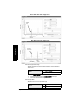
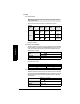

Table Of Contents
- Table of Contents
- SITRANS LR260 Overview
- Specifications
- Installation
- Wiring
- Quick Start via local operation
- Operating via SIMATIC PDM
- Parameter Reference
- Pull-down menus via SIMATIC PDM
- Quick Start Wizard
- 1. Quick Start
- 2. Setup
- 3. Diagnostics
- 3.1. Echo Profile
- 3.14. Measured Values (MEAS. VALUES)
- 3.15. Remaining Device Lifetime (REMAIN. DEV. LIFE.)
- 3.15.2. Remaining Device Lifetime (REMAIN. LIFETIME)
- 3.15.3. Maintenance Required Limit (MAINT. REQ. LIMIT)
- 3.15.4. Maintenance Demanded Limit (MAINT. DEM. LIMIT)
- 3.15.5. Maintenance Alert Activation (ALERT ACTIVATION)
- 3.15.6. Total Expected Device Life (TOTAL EXP. LIFE)
- 3.15.7. Maintenance Status (MAINT. STAT.)
- 3.15.8. Acknowledge Status (ACK STATUS)
- 3.15.9. Acknowledge (ACK)
- 3.16. Remaining Sensor Lifetime (REMAIN SENS. LIFE.)
- 3.16.2. Remaining Sensor Lifetime (REMAIN. LIFETIME)
- 3.16.3. Maintenance Required Limit (MAINT. REQ. LIMIT)
- 3.16.4. Maintenance Demanded Limit (MAINT. DEM. LIMIT)
- 3.16.5. Maintenance Alert Activation (ALERT ACTIVATION)
- 3.16.6. Total Expected Sensor Life (TOTAL. EXP. LIFE)
- 3.16.7. Maintenance Status (MAINT. STATUS)
- 3.16.8. Acknowledge Status (ACK. STATUS)
- 3.16.9. Acknowledge (ACK.)
- 4. Service
- 4.1. Device Reset
- 4.2. Manufacture Date (MANUF. DATE)
- 4.3. LCD Fast Mode
- 4.4. LCD Contrast
- 4.11. Memory Test (MEM. TEST)
- 4.16.1. Time Last Serviced (TIME LAST SERV.)
- 4.16.2. Remaining Lifetime (REMAIN LIFETIME)
- 4.16.3. Maintenance Required Limit (MAINT. REQ. LIMIT)
- 4.16.4. Maintenance Demanded Limit
- 4.16.5. Maintenance Alert Activation
- 4.16.6. Total Service Interval
- 4.16.7. Maintenance Status (MAINT. STAT)
- 4.16.8. Acknowledge Status (ACK. STATUS)
- 4.16.9. Acknowledge (ACK.)
- 4.17. Calibration Interval (CALIB. INTERVAL)
- 4.17.1. Time Last Calibrated (TIME LAST CAL.)
- 4.17.2. Remaining Lifetime (REMAIN LIFETIME)
- 4.17.3. Maintenance Required Limit (MAINT. REQ. LIMIT)
- 4.17.4. Maintenance Demanded Limit (MAINT. DEM. LIMIT)
- 4.17.5. Maintenance Alert Activation
- 4.17.6. Total Calibration Interval (TOTAL CALIB. INTRV.)
- 4.17.7. Maintenance Status (MAINT. STAT.)
- 4.17.8. Acknowledge Status (ACK. STATUS)
- 4.17.9. Acknowledge (ACK.)
- 5. Communication
- 6. Security
- 7. Language
- Appendix A: Alphabetical Parameter List
- Appendix B: Troubleshooting
- Appendix C: Maintenance
- Appendix D: Technical Reference
- Appendix E: Application Example
- Appendix F: HART Communications
- Appendix G: Firmware Revision History
- Glossary
- Index
- LCD menu structure

A5E32337683 SITRANS LR260 (HART) – OPERATING INSTRUCTIONS Page 59
mmmmm
Parameters
2.2.5. TVT (Auto False Echo Suppression) setup (TVT SETUP)
First SITRANS LR260 learns the echo profile. Then the learned profile, or part
of the learned profile, is used to screen out false echoes. See Before and After
Auto False Echo Suppression on page 60 for examples.
2.2.5.1. TVT Hover Level
Defines how high the TVT (Time Varying Threshold) curve is placed above
the noise floor of the echo profile, as a percentage of the difference between
the peak of the largest echo in the profile and the noise floor. When
SITRANS LR260 is located in the center of the vessel, the TVT hover level
may be lowered to increase the confidence level of the largest echo.
(For an
illustration of the TVT curve see
Before Auto False Echo Suppression on
page 60.)
2.2.5.2. Auto False Echo Suppression
Enables a ’learned’ TVT curve to be used in place of the default TVT curve.
(See Auto False Echo Suppression on page 98 for an explanation)
a. Determine Range (the distance within which the learned TVT will
replace the default TVT). Measure the actual distance from the
sensor reference point to the material surface using a rope or tape
measure, and make allowances for the actual location of the
device.
b. Subtract 2 m (6.56 ft) from this distance, and use the resulting value.
To use Auto False Echo Suppression via SIMATIC PDM:
c. Open the menu Device – Auto False Echo Suppression and set
Range. For more detail see
Auto False Echo Suppression
on page 44.
d. Select Learn. The device will automatically revert to On (Use
Learned TVT) after a few seconds.
To set Auto False Echo Suppression via the handheld programmer:
c. Go to
2.2.5.3. Auto Suppression Range
and enter new value.
d. Go to
2.2.5.2. Auto False Echo Suppression
. Press RIGHT ARROW to
open Edit Mode
e. Select Learn. The device will automatically revert to On (Use
Learned TVT) after a few seconds.
Values
Range: 0 to 100%
Default: 33%
Notes:
• If possible adjust Auto False Echo Suppression parameters with an
empty or almost empty vessel.
• Set Auto False Echo Suppression and Auto False Echo Range during
startup, if possible.
Options
OFF Default TVT curve will be used.
* ON ’Learned’ TVT curve will be used.
LEARN ’Learn’ the TVT curve.