
User's Manual
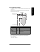
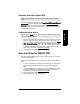

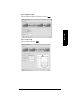
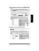
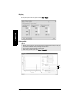
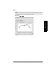
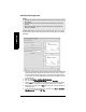
Table Of Contents
- Table of Contents
- SITRANS LR260 Overview
- Specifications
- Installation
- Wiring
- Quick Start via local operation
- Operating via SIMATIC PDM
- Parameter Reference
- Pull-down menus via SIMATIC PDM
- Quick Start Wizard
- 1. Quick Start
- 2. Setup
- 3. Diagnostics
- 3.1. Echo Profile
- 3.14. Measured Values (MEAS. VALUES)
- 3.15. Remaining Device Lifetime (REMAIN. DEV. LIFE.)
- 3.15.2. Remaining Device Lifetime (REMAIN. LIFETIME)
- 3.15.3. Maintenance Required Limit (MAINT. REQ. LIMIT)
- 3.15.4. Maintenance Demanded Limit (MAINT. DEM. LIMIT)
- 3.15.5. Maintenance Alert Activation (ALERT ACTIVATION)
- 3.15.6. Total Expected Device Life (TOTAL EXP. LIFE)
- 3.15.7. Maintenance Status (MAINT. STAT.)
- 3.15.8. Acknowledge Status (ACK STATUS)
- 3.15.9. Acknowledge (ACK)
- 3.16. Remaining Sensor Lifetime (REMAIN SENS. LIFE.)
- 3.16.2. Remaining Sensor Lifetime (REMAIN. LIFETIME)
- 3.16.3. Maintenance Required Limit (MAINT. REQ. LIMIT)
- 3.16.4. Maintenance Demanded Limit (MAINT. DEM. LIMIT)
- 3.16.5. Maintenance Alert Activation (ALERT ACTIVATION)
- 3.16.6. Total Expected Sensor Life (TOTAL. EXP. LIFE)
- 3.16.7. Maintenance Status (MAINT. STATUS)
- 3.16.8. Acknowledge Status (ACK. STATUS)
- 3.16.9. Acknowledge (ACK.)
- 4. Service
- 4.1. Device Reset
- 4.2. Manufacture Date (MANUF. DATE)
- 4.3. LCD Fast Mode
- 4.4. LCD Contrast
- 4.11. Memory Test (MEM. TEST)
- 4.16.1. Time Last Serviced (TIME LAST SERV.)
- 4.16.2. Remaining Lifetime (REMAIN LIFETIME)
- 4.16.3. Maintenance Required Limit (MAINT. REQ. LIMIT)
- 4.16.4. Maintenance Demanded Limit
- 4.16.5. Maintenance Alert Activation
- 4.16.6. Total Service Interval
- 4.16.7. Maintenance Status (MAINT. STAT)
- 4.16.8. Acknowledge Status (ACK. STATUS)
- 4.16.9. Acknowledge (ACK.)
- 4.17. Calibration Interval (CALIB. INTERVAL)
- 4.17.1. Time Last Calibrated (TIME LAST CAL.)
- 4.17.2. Remaining Lifetime (REMAIN LIFETIME)
- 4.17.3. Maintenance Required Limit (MAINT. REQ. LIMIT)
- 4.17.4. Maintenance Demanded Limit (MAINT. DEM. LIMIT)
- 4.17.5. Maintenance Alert Activation
- 4.17.6. Total Calibration Interval (TOTAL CALIB. INTRV.)
- 4.17.7. Maintenance Status (MAINT. STAT.)
- 4.17.8. Acknowledge Status (ACK. STATUS)
- 4.17.9. Acknowledge (ACK.)
- 5. Communication
- 6. Security
- 7. Language
- Appendix A: Alphabetical Parameter List
- Appendix B: Troubleshooting
- Appendix C: Maintenance
- Appendix D: Technical Reference
- Appendix E: Application Example
- Appendix F: HART Communications
- Appendix G: Firmware Revision History
- Glossary
- Index
- LCD menu structure

Page 44 SITRANS LR260 (HART) – OPERATING INSTRUCTIONS A5E32337683
mmmmm
SIMATIC PDM
Auto False Echo Suppression
SITRANS LR260 first learns the echo profile. Then the learned profile, or part of it, is used to
screen out false echoes. (See
Auto False Echo Suppression
on page 98 for a more detailed
explanation.)
1. Determine Auto Suppression Range (the distance within which the learned TVT will
replace the default TVT). Measure the actual distance from the antenna reference
point to the material surface using a rope or tape measure, and make allowances
for the actual location of the LR260. Subtract 2 m (6.56 ft) from this distance, and use
the resulting value.
2. Open the menu Device – Auto False Echo Suppression.
3. Enter the value for Auto Suppression Range and click on Set Range.
4. Click on Learn. While the new curve is being learned, all buttons are inaccessible.
Unless calculation is instantaneous, buttons will disappear until it is complete.
5. When buttons are visible, click on Close. Auto TVT is now on, and the learned TVT
curve will be used.
6. To turn Auto False Echo Suppression off or on, reopen menu Device – Auto False
Echo Suppression and click on Off or On.
Notes:
• If possible, adjust Auto False Echo Suppression parameters with an empty or almost
empty vessel.
• Set Auto False Echo Suppression and Auto Suppression Range during startup, if
possible.
• Before adjusting these parameters, rotate the instrument for best signal (lower
false-echo amplitude).