
User's Manual

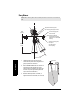


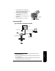
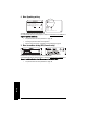
Table Of Contents
- Table of Contents
- SITRANS LR260 Overview
- Specifications
- Installation
- Wiring
- Quick Start via local operation
- Operating via SIMATIC PDM
- Parameter Reference
- Pull-down menus via SIMATIC PDM
- Quick Start Wizard
- 1. Quick Start
- 2. Setup
- 3. Diagnostics
- 3.1. Echo Profile
- 3.14. Measured Values (MEAS. VALUES)
- 3.15. Remaining Device Lifetime (REMAIN. DEV. LIFE.)
- 3.15.2. Remaining Device Lifetime (REMAIN. LIFETIME)
- 3.15.3. Maintenance Required Limit (MAINT. REQ. LIMIT)
- 3.15.4. Maintenance Demanded Limit (MAINT. DEM. LIMIT)
- 3.15.5. Maintenance Alert Activation (ALERT ACTIVATION)
- 3.15.6. Total Expected Device Life (TOTAL EXP. LIFE)
- 3.15.7. Maintenance Status (MAINT. STAT.)
- 3.15.8. Acknowledge Status (ACK STATUS)
- 3.15.9. Acknowledge (ACK)
- 3.16. Remaining Sensor Lifetime (REMAIN SENS. LIFE.)
- 3.16.2. Remaining Sensor Lifetime (REMAIN. LIFETIME)
- 3.16.3. Maintenance Required Limit (MAINT. REQ. LIMIT)
- 3.16.4. Maintenance Demanded Limit (MAINT. DEM. LIMIT)
- 3.16.5. Maintenance Alert Activation (ALERT ACTIVATION)
- 3.16.6. Total Expected Sensor Life (TOTAL. EXP. LIFE)
- 3.16.7. Maintenance Status (MAINT. STATUS)
- 3.16.8. Acknowledge Status (ACK. STATUS)
- 3.16.9. Acknowledge (ACK.)
- 4. Service
- 4.1. Device Reset
- 4.2. Manufacture Date (MANUF. DATE)
- 4.3. LCD Fast Mode
- 4.4. LCD Contrast
- 4.11. Memory Test (MEM. TEST)
- 4.16.1. Time Last Serviced (TIME LAST SERV.)
- 4.16.2. Remaining Lifetime (REMAIN LIFETIME)
- 4.16.3. Maintenance Required Limit (MAINT. REQ. LIMIT)
- 4.16.4. Maintenance Demanded Limit
- 4.16.5. Maintenance Alert Activation
- 4.16.6. Total Service Interval
- 4.16.7. Maintenance Status (MAINT. STAT)
- 4.16.8. Acknowledge Status (ACK. STATUS)
- 4.16.9. Acknowledge (ACK.)
- 4.17. Calibration Interval (CALIB. INTERVAL)
- 4.17.1. Time Last Calibrated (TIME LAST CAL.)
- 4.17.2. Remaining Lifetime (REMAIN LIFETIME)
- 4.17.3. Maintenance Required Limit (MAINT. REQ. LIMIT)
- 4.17.4. Maintenance Demanded Limit (MAINT. DEM. LIMIT)
- 4.17.5. Maintenance Alert Activation
- 4.17.6. Total Calibration Interval (TOTAL CALIB. INTRV.)
- 4.17.7. Maintenance Status (MAINT. STAT.)
- 4.17.8. Acknowledge Status (ACK. STATUS)
- 4.17.9. Acknowledge (ACK.)
- 5. Communication
- 6. Security
- 7. Language
- Appendix A: Alphabetical Parameter List
- Appendix B: Troubleshooting
- Appendix C: Maintenance
- Appendix D: Technical Reference
- Appendix E: Application Example
- Appendix F: HART Communications
- Appendix G: Firmware Revision History
- Glossary
- Index
- LCD menu structure

Page 18 SITRANS LR260 (HART) – OPERATING INSTRUCTIONS A5E32337683
mmmmm
Installation
Universal Slotted Flange
Slotted Flange Dimensions
1)
WARNING: The user is responsible for the selection of bolting and
gasket materials which will fall within the limits of the flange and its
intended use and which are suitable for the service conditions.
Pipe
Size
Flange
O.D.
Thick-
ness (s)
Bolt Hole
Circle Max Ø
Bolt Hole
Circle Min Ø
Bolt Hole
radius
No. of
Slotted
Holes
2" or
50 mm
6.50"
(165 mm)
0.38"
(9.65 mm)
4.92"
(125 mm)
4.72"
(120 mm)
0.38"
(9.65 mm)
4
3" or
80 mm
7.87"
(200 mm)
0.38"
(9.65 mm)
6.30"
(160 mm)
5.91"
(150 mm)
0.38"
(9.65 mm)
8
4" or
100 mm
9.00"
(229 mm)
0.38"
(9.65 mm)
7.52"
(191 mm)
6.89"
(175 mm)
0.38"
(9.65 mm)
8
6" or
150 mm
11.22"
(285 mm)
0.38"
(9.65 mm)
9.53"
(242 mm)
9.45"
(240 mm)
0.45"
(11.5 mm)
8
1)
Universal flange mates with EN 1092-1 (PN16)/ASME B16.5 (150 lb)/JIS 2220 (10K) bolt
hole pattern.
flange O.D.
bolt hole circle
min. diameter
number of slotted bolt holes
section A-A
thickness
bolt hole circle max. diameter