
User's Manual

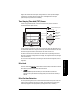

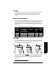


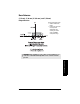
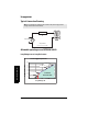
Table Of Contents
- Table of Contents
- SITRANS LR260 Overview
- Specifications
- Installation
- Wiring
- Quick Start via local operation
- Operating via SIMATIC PDM
- Parameter Reference
- Pull-down menus via SIMATIC PDM
- Quick Start Wizard
- 1. Quick Start
- 2. Setup
- 3. Diagnostics
- 3.1. Echo Profile
- 3.14. Measured Values (MEAS. VALUES)
- 3.15. Remaining Device Lifetime (REMAIN. DEV. LIFE.)
- 3.15.2. Remaining Device Lifetime (REMAIN. LIFETIME)
- 3.15.3. Maintenance Required Limit (MAINT. REQ. LIMIT)
- 3.15.4. Maintenance Demanded Limit (MAINT. DEM. LIMIT)
- 3.15.5. Maintenance Alert Activation (ALERT ACTIVATION)
- 3.15.6. Total Expected Device Life (TOTAL EXP. LIFE)
- 3.15.7. Maintenance Status (MAINT. STAT.)
- 3.15.8. Acknowledge Status (ACK STATUS)
- 3.15.9. Acknowledge (ACK)
- 3.16. Remaining Sensor Lifetime (REMAIN SENS. LIFE.)
- 3.16.2. Remaining Sensor Lifetime (REMAIN. LIFETIME)
- 3.16.3. Maintenance Required Limit (MAINT. REQ. LIMIT)
- 3.16.4. Maintenance Demanded Limit (MAINT. DEM. LIMIT)
- 3.16.5. Maintenance Alert Activation (ALERT ACTIVATION)
- 3.16.6. Total Expected Sensor Life (TOTAL. EXP. LIFE)
- 3.16.7. Maintenance Status (MAINT. STATUS)
- 3.16.8. Acknowledge Status (ACK. STATUS)
- 3.16.9. Acknowledge (ACK.)
- 4. Service
- 4.1. Device Reset
- 4.2. Manufacture Date (MANUF. DATE)
- 4.3. LCD Fast Mode
- 4.4. LCD Contrast
- 4.11. Memory Test (MEM. TEST)
- 4.16.1. Time Last Serviced (TIME LAST SERV.)
- 4.16.2. Remaining Lifetime (REMAIN LIFETIME)
- 4.16.3. Maintenance Required Limit (MAINT. REQ. LIMIT)
- 4.16.4. Maintenance Demanded Limit
- 4.16.5. Maintenance Alert Activation
- 4.16.6. Total Service Interval
- 4.16.7. Maintenance Status (MAINT. STAT)
- 4.16.8. Acknowledge Status (ACK. STATUS)
- 4.16.9. Acknowledge (ACK.)
- 4.17. Calibration Interval (CALIB. INTERVAL)
- 4.17.1. Time Last Calibrated (TIME LAST CAL.)
- 4.17.2. Remaining Lifetime (REMAIN LIFETIME)
- 4.17.3. Maintenance Required Limit (MAINT. REQ. LIMIT)
- 4.17.4. Maintenance Demanded Limit (MAINT. DEM. LIMIT)
- 4.17.5. Maintenance Alert Activation
- 4.17.6. Total Calibration Interval (TOTAL CALIB. INTRV.)
- 4.17.7. Maintenance Status (MAINT. STAT.)
- 4.17.8. Acknowledge Status (ACK. STATUS)
- 4.17.9. Acknowledge (ACK.)
- 5. Communication
- 6. Security
- 7. Language
- Appendix A: Alphabetical Parameter List
- Appendix B: Troubleshooting
- Appendix C: Maintenance
- Appendix D: Technical Reference
- Appendix E: Application Example
- Appendix F: HART Communications
- Appendix G: Firmware Revision History
- Glossary
- Index
- LCD menu structure

Page 100 SITRANS LR260 (HART) – OPERATING INSTRUCTIONS A5E32337683
mmmmm
D: Technical Reference
When the instrument is returned to Measurement mode, the transceiver resumes
operation. The reading and mA output default to the last measurement taken. The reading
and associated outputs migrate to the current process level at a rate controlled by the
response rate (2.2.7.1).
If SITRANS LR260 is left in PROGRAM
mode for 10 minutes without input, it automatically
reverts to Measurement mode.
Damping
A damping filter smooths out the response to a sudden change in level. This is an
exponential filter and the engineering unit is always in seconds. The setting can be
modified in
2.2.4.3.2. Damping Filter
.
Damping example
Loss of Echo (LOE)
A loss of echo (LOE) occurs when the calculated measurement is judged to be unreliable
because the echo confidence value has dropped below the echo confidence threshold.
If the LOE condition persists beyond the time limit set in
2.4.1. Fail-safe Timer
the LCD
displays the Maintenance Required icon, and the text region displays the fault code S: 0
and the text LOE.
If two faults are present at the same time, the fault code, error text, and error icon for
each fault are displayed alternately. For example, Loss of Echo and Fail-safe High.
S: 0 LOE S: 52 FAIL-SAFE
Fail-safe Mode
The purpose of the Fail-safe setting is to put the process into a safe mode of operation in
the event of a fault or failure. The value to be reported in the event of a fault is selected so
that a loss of power or loss of signal triggers the same response as an unsafe level.
0
0.5
1
1.5
2
2.5
3
3.5
4
4.5
1234567
Series1 Seri es 2
time constant = 2 seconds
input (level) change = 2 m
In 5 time constants the output rises
exponentially:
from 63.2% of the change in the
first time constant, to almost 100%
of the change by the end of the 5th
time constant.
Level (m)
Time (s)
smoothed
output
input
(level)