
User's Manual

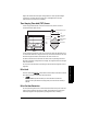

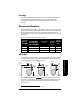


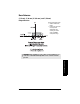
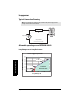
Table Of Contents
- Table of Contents
- SITRANS LR260 Overview
- Specifications
- Installation
- Wiring
- Quick Start via local operation
- Operating via SIMATIC PDM
- Parameter Reference
- Pull-down menus via SIMATIC PDM
- Quick Start Wizard
- 1. Quick Start
- 2. Setup
- 3. Diagnostics
- 3.1. Echo Profile
- 3.14. Measured Values (MEAS. VALUES)
- 3.15. Remaining Device Lifetime (REMAIN. DEV. LIFE.)
- 3.15.2. Remaining Device Lifetime (REMAIN. LIFETIME)
- 3.15.3. Maintenance Required Limit (MAINT. REQ. LIMIT)
- 3.15.4. Maintenance Demanded Limit (MAINT. DEM. LIMIT)
- 3.15.5. Maintenance Alert Activation (ALERT ACTIVATION)
- 3.15.6. Total Expected Device Life (TOTAL EXP. LIFE)
- 3.15.7. Maintenance Status (MAINT. STAT.)
- 3.15.8. Acknowledge Status (ACK STATUS)
- 3.15.9. Acknowledge (ACK)
- 3.16. Remaining Sensor Lifetime (REMAIN SENS. LIFE.)
- 3.16.2. Remaining Sensor Lifetime (REMAIN. LIFETIME)
- 3.16.3. Maintenance Required Limit (MAINT. REQ. LIMIT)
- 3.16.4. Maintenance Demanded Limit (MAINT. DEM. LIMIT)
- 3.16.5. Maintenance Alert Activation (ALERT ACTIVATION)
- 3.16.6. Total Expected Sensor Life (TOTAL. EXP. LIFE)
- 3.16.7. Maintenance Status (MAINT. STATUS)
- 3.16.8. Acknowledge Status (ACK. STATUS)
- 3.16.9. Acknowledge (ACK.)
- 4. Service
- 4.1. Device Reset
- 4.2. Manufacture Date (MANUF. DATE)
- 4.3. LCD Fast Mode
- 4.4. LCD Contrast
- 4.11. Memory Test (MEM. TEST)
- 4.16.1. Time Last Serviced (TIME LAST SERV.)
- 4.16.2. Remaining Lifetime (REMAIN LIFETIME)
- 4.16.3. Maintenance Required Limit (MAINT. REQ. LIMIT)
- 4.16.4. Maintenance Demanded Limit
- 4.16.5. Maintenance Alert Activation
- 4.16.6. Total Service Interval
- 4.16.7. Maintenance Status (MAINT. STAT)
- 4.16.8. Acknowledge Status (ACK. STATUS)
- 4.16.9. Acknowledge (ACK.)
- 4.17. Calibration Interval (CALIB. INTERVAL)
- 4.17.1. Time Last Calibrated (TIME LAST CAL.)
- 4.17.2. Remaining Lifetime (REMAIN LIFETIME)
- 4.17.3. Maintenance Required Limit (MAINT. REQ. LIMIT)
- 4.17.4. Maintenance Demanded Limit (MAINT. DEM. LIMIT)
- 4.17.5. Maintenance Alert Activation
- 4.17.6. Total Calibration Interval (TOTAL CALIB. INTRV.)
- 4.17.7. Maintenance Status (MAINT. STAT.)
- 4.17.8. Acknowledge Status (ACK. STATUS)
- 4.17.9. Acknowledge (ACK.)
- 5. Communication
- 6. Security
- 7. Language
- Appendix A: Alphabetical Parameter List
- Appendix B: Troubleshooting
- Appendix C: Maintenance
- Appendix D: Technical Reference
- Appendix E: Application Example
- Appendix F: HART Communications
- Appendix G: Firmware Revision History
- Glossary
- Index
- LCD menu structure

A5E32337683 SITRANS LR260 (HART) – OPERATING INSTRUCTIONS Page 99
mmmmm
D: Technical Reference
Far Range
In applications where the base of the vessel is conical or parabolic, a reliable echo may
be available below the vessel empty distance, due to an indirect reflection path.
Increasing the range extension to 30% or 40% can provide stable empty vessel
readings.
1)
Measurement Response
The measurement response (response rate) limits the maximum rate at which the display
and output respond to changes in the measurement. Once the real process fill/empty rate
(m/s) is established, a response rate can be selected that is slightly higher than the
application rate. The response rate automatically adjusts the filters that affect the output
response rate.
There are three preset options: slow, medium, and fast.
mA Output
The mA output is proportional to the level, in the range 4 to 20 mA. Generally, the output is
set so that the output for 0% is 4 mA, and the output for 100% is 20 mA. 0 and 100% are
percentages of the full-scale reading (m, cm, mm, ft, in).
When SITRANS LR260 is put into PROGRAM mode it stops responding to the process. It
stores the most recent measurement, and holds the associated readings and mA signal
output. The instrument reverts to the parameter last addressed during the previous
program session.
1)
On 30 m vessel, range extension cannot exceed 31.5 m.
2.2.7.2. Fill
Rate (FILL
RATE/MIN)
2.2.7.2. Fill Rate
(FILL RATE/MIN)
/
2.2.7.3. Empty rate
(EMPTY RATE/MIN)
2.2.4.2.1. Echo
Lock
2.4.1. Fail-
safe Timer
(time in
min.)
2.2.4.3.2.
Damping
Filter
Slow 0.1 m/min MAX. VERFICATION 100 60
Medium 1 m/min MAX. VERFICATION 10 10
Fast * 10 m/min MAX. VERFICATION 1 0
Level Space
Distance
Distance
Space
Level
20 mA
100%
0%
4 mA
High
Cal.
Point
4 mA
0%
100%
20 mA
4 mA
0%
100%
20 mA
Sensor
reference
point
Low
Cal.
Point