
User's Manual

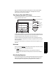

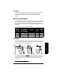

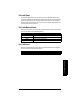

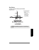
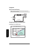
Table Of Contents
- Table of Contents
- SITRANS LR260 Overview
- Specifications
- Installation
- Wiring
- Quick Start via local operation
- Operating via SIMATIC PDM
- Parameter Reference
- Pull-down menus via SIMATIC PDM
- Quick Start Wizard
- 1. Quick Start
- 2. Setup
- 3. Diagnostics
- 3.1. Echo Profile
- 3.14. Measured Values (MEAS. VALUES)
- 3.15. Remaining Device Lifetime (REMAIN. DEV. LIFE.)
- 3.15.2. Remaining Device Lifetime (REMAIN. LIFETIME)
- 3.15.3. Maintenance Required Limit (MAINT. REQ. LIMIT)
- 3.15.4. Maintenance Demanded Limit (MAINT. DEM. LIMIT)
- 3.15.5. Maintenance Alert Activation (ALERT ACTIVATION)
- 3.15.6. Total Expected Device Life (TOTAL EXP. LIFE)
- 3.15.7. Maintenance Status (MAINT. STAT.)
- 3.15.8. Acknowledge Status (ACK STATUS)
- 3.15.9. Acknowledge (ACK)
- 3.16. Remaining Sensor Lifetime (REMAIN SENS. LIFE.)
- 3.16.2. Remaining Sensor Lifetime (REMAIN. LIFETIME)
- 3.16.3. Maintenance Required Limit (MAINT. REQ. LIMIT)
- 3.16.4. Maintenance Demanded Limit (MAINT. DEM. LIMIT)
- 3.16.5. Maintenance Alert Activation (ALERT ACTIVATION)
- 3.16.6. Total Expected Sensor Life (TOTAL. EXP. LIFE)
- 3.16.7. Maintenance Status (MAINT. STATUS)
- 3.16.8. Acknowledge Status (ACK. STATUS)
- 3.16.9. Acknowledge (ACK.)
- 4. Service
- 4.1. Device Reset
- 4.2. Manufacture Date (MANUF. DATE)
- 4.3. LCD Fast Mode
- 4.4. LCD Contrast
- 4.11. Memory Test (MEM. TEST)
- 4.16.1. Time Last Serviced (TIME LAST SERV.)
- 4.16.2. Remaining Lifetime (REMAIN LIFETIME)
- 4.16.3. Maintenance Required Limit (MAINT. REQ. LIMIT)
- 4.16.4. Maintenance Demanded Limit
- 4.16.5. Maintenance Alert Activation
- 4.16.6. Total Service Interval
- 4.16.7. Maintenance Status (MAINT. STAT)
- 4.16.8. Acknowledge Status (ACK. STATUS)
- 4.16.9. Acknowledge (ACK.)
- 4.17. Calibration Interval (CALIB. INTERVAL)
- 4.17.1. Time Last Calibrated (TIME LAST CAL.)
- 4.17.2. Remaining Lifetime (REMAIN LIFETIME)
- 4.17.3. Maintenance Required Limit (MAINT. REQ. LIMIT)
- 4.17.4. Maintenance Demanded Limit (MAINT. DEM. LIMIT)
- 4.17.5. Maintenance Alert Activation
- 4.17.6. Total Calibration Interval (TOTAL CALIB. INTRV.)
- 4.17.7. Maintenance Status (MAINT. STAT.)
- 4.17.8. Acknowledge Status (ACK. STATUS)
- 4.17.9. Acknowledge (ACK.)
- 5. Communication
- 6. Security
- 7. Language
- Appendix A: Alphabetical Parameter List
- Appendix B: Troubleshooting
- Appendix C: Maintenance
- Appendix D: Technical Reference
- Appendix E: Application Example
- Appendix F: HART Communications
- Appendix G: Firmware Revision History
- Glossary
- Index
- LCD menu structure

Page 98 SITRANS LR260 (HART) – OPERATING INSTRUCTIONS A5E32337683
mmmmm
D: Technical Reference
The options are Center, CLEF (Constrained Leading Edge Fit), Hybrid or Rising Edge. CLEF
uses the leading edge of the echo. It can be used to compensate for materials with a low
dK value, which may cause the vessel bottom to be reported as the level instead of the
actual material level, in low level conditions. CLEF range is the level below which the
CLEF algorithm will be used: above this level the Center algorithm is used.
Hybrid uses a combination of Center and CLEF, depending on the setting for CLEF range.
Auto False Echo Suppression
If an obstruction is causing a large echo before the material level echo, that echo will rise
above the default TVT curve and may be selected as the true echo. Auto False-Echo
Suppression modifies the TVT curve so that the false echo will not rise above the TVT
curve.
When you use Auto False Echo Suppression, the device first learns the echo profile at
that moment
1)
. A learned TVT curve follows the echo profile and rises above the false
echo. You set Auto Suppression Range so that the learned profile replaces the default
TVT curve up to a point past the obstruction. From that point on, the default TVT curve is
used. The material level echo rises above this, and is selected as the true echo.
Measurement Range
Near Range
2.2.1.12. Near Range
programs SITRANS LR260 to ignore the zone in front of the antenna.
The default blanking distance is 50 mm (1.97") from end of horn antenna.
Near Range allows you to increase the blanking value from its factory default. But
2.2.5.2.
Auto False Echo Suppression
is generally recommended in preference to extending the
blanking distance from factory values.
1)
Use Auto False Echo Suppression when the material level is substantially lower than pro-
cess full level (ideally when the tank is empty or almost empty).
Example after Auto False Echo Suppression
learned
TVT curve
level
Level (db)
false echo
echo marker